Power Steering Rack & Pinion Assembly
Variant note: this section covers the power-assisted steering rack, as distinct from Manual Steering Rack & Pinion Assembly: Overhaul. Not confirmed which steering type equips our specific truck (VR-II, 4A30 DOHC turbo, 3A/T, 4WD) — verify by physical inspection (power steering pump/belt/reservoir present on the engine) or EPC parts catalog cross-check before relying on this section. (verify: manual vs. power steering on our truck)
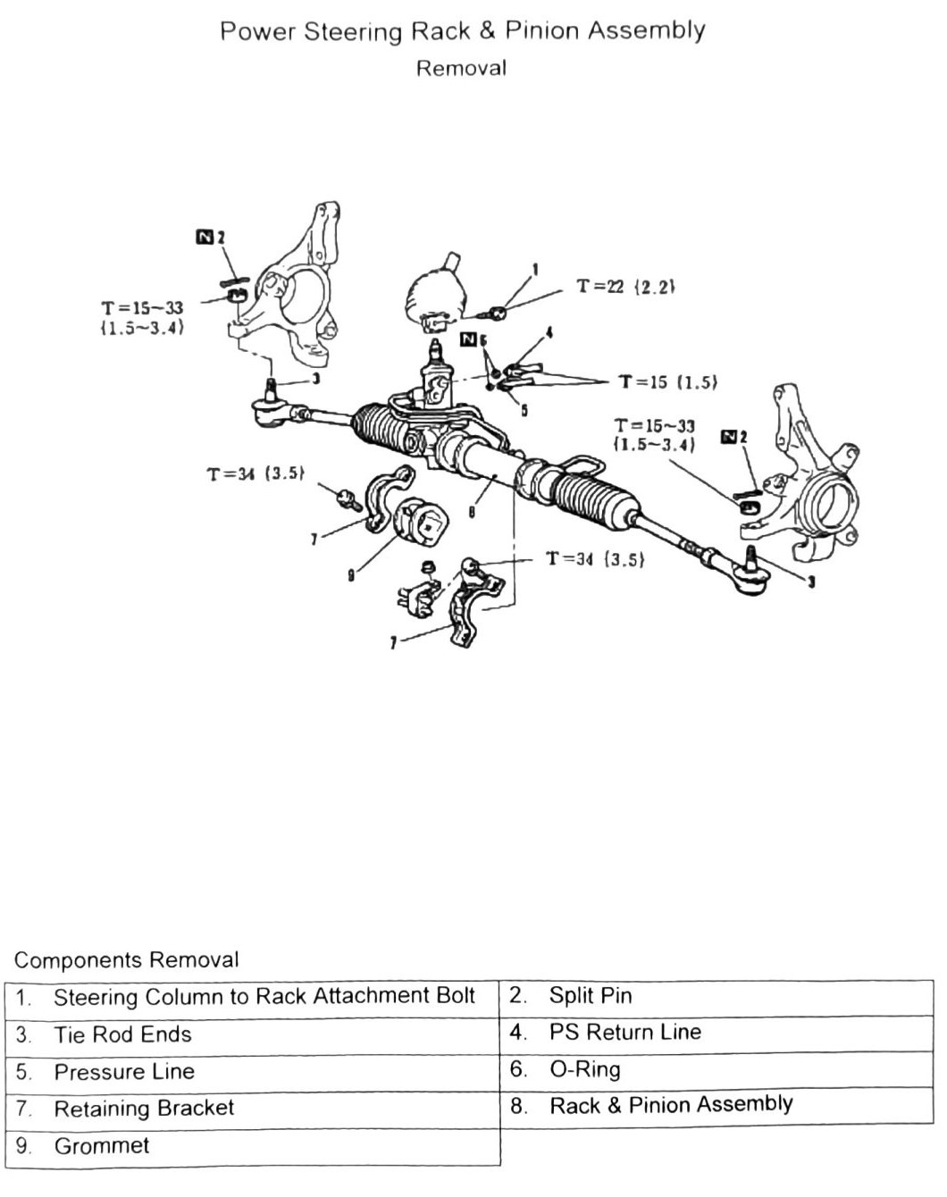
Removal (printed p.297)
Components
| # | Component |
|---|---|
| 1 | Steering Column to Rack Attachment Bolt |
| 2 | Split Pin |
| 3 | Tie Rod Ends |
| 4 | PS Return Line |
| 5 | Pressure Line |
| 6 | O-Ring |
| 7 | Retaining Bracket |
| 8 | Rack & Pinion Assembly |
| 9 | Grommet |
Torque specifications
| Fastener | Torque |
|---|---|
| Fastener (unlabeled) | 22 N·m (2.2 kgf·m; 16 ft-lb) |
| Fastener (unlabeled, ×2 locations) | 15-33 N·m (1.5-3.4 kgf·m; 11-24 ft-lb) |
| Fastener (unlabeled) | 15 N·m (1.5 kgf·m; 133 in-lb) |
| Fastener (unlabeled, ×2 locations) | 34 N·m (3.5 kgf·m; 25 ft-lb) |
OCR note: fastener assignment for the torque values above is not legible from the scan. (verify printed p.297)
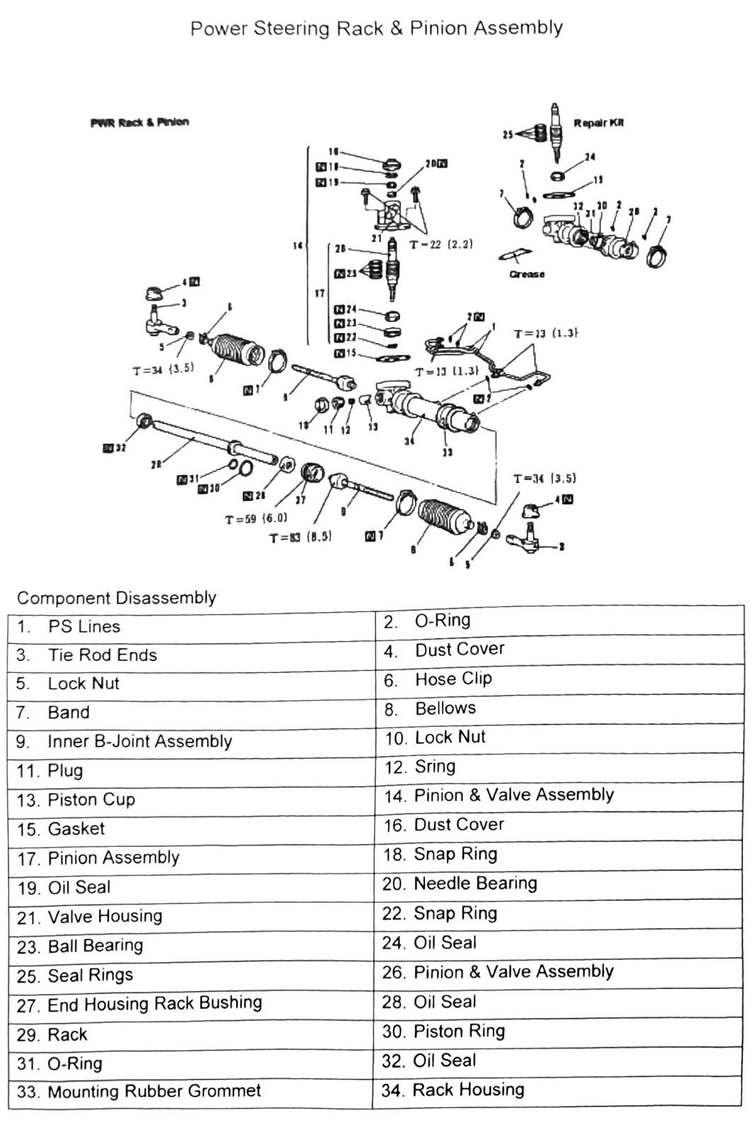
Repair kit components (printed p.298)
| # | Component | # | Component |
|---|---|---|---|
| 1 | PS Lines | 2 | O-Ring |
| 3 | Tie Rod Ends | 4 | Dust Cover |
| 5 | Lock Nut | 6 | Hose Clip |
| 7 | Band | 8 | Bellows |
| 9 | Inner B-Joint Assembly | 10 | Lock Nut |
| 11 | Plug | 12 | Spring |
| 13 | Piston Cup | 14 | Pinion & Valve Assembly |
| 15 | Gasket | 16 | Dust Cover |
| 17 | Pinion Assembly | 18 | Snap Ring |
| 19 | Oil Seal | 20 | Needle Bearing |
| 21 | Valve Housing | 22 | Snap Ring |
| 23 | Ball Bearing | 24 | Oil Seal |
| 25 | Seal Rings | 26 | Pinion & Valve Assembly |
| 27 | End Housing Rack Bushing | 28 | Oil Seal |
| 29 | Rack | 30 | Piston Ring |
| 31 | O-Ring | 32 | Oil Seal |
| 33 | Mounting Rubber Grommet | 34 | Rack Housing |
OCR note: items 14 and 26 both transcribed as “Pinion & Valve Assembly” — likely one of the two is a distinct sub-component (e.g., valve body vs. pinion shaft alone) that got OCR’d identically. (verify printed p.298) for the correct distinct name of item 26.
Torque specifications
| Fastener | Torque |
|---|---|
| Fastener (unlabeled) | 22 N·m (2.2 kgf·m; 16 ft-lb) |
| Fastener (unlabeled, ×2 locations) | 13 N·m (1.3 kgf·m; 115 in-lb) |
| Fastener (unlabeled, ×2 locations) | 34 N·m (3.5 kgf·m; 25 ft-lb) |
| Fastener (unlabeled) | 59 N·m (6.0 kgf·m; 44 ft-lb) |
| Fastener (unlabeled) | 83 N·m (8.5 kgf·m; 61 ft-lb) |
OCR note: fastener assignment for the torque values above is not legible from the scan. (verify printed p.298)
Overhaul — disassembly (printed p.299-300)
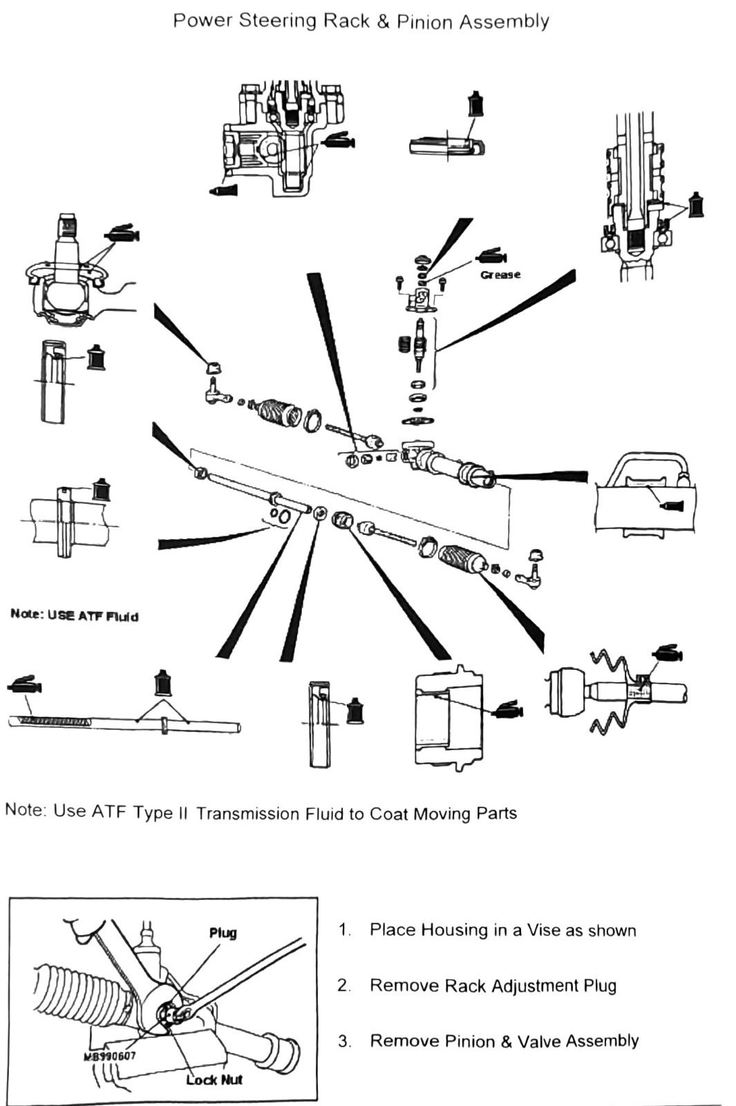
Note: use ATF (Automatic Transmission Fluid) — specifically ATF Type II only, not ATF-SP, to coat moving parts during reassembly (called out again below).
- Place housing in a vise as shown.
- Remove rack adjustment plug (tool MB990607, lock nut).
- Remove pinion & valve assembly.
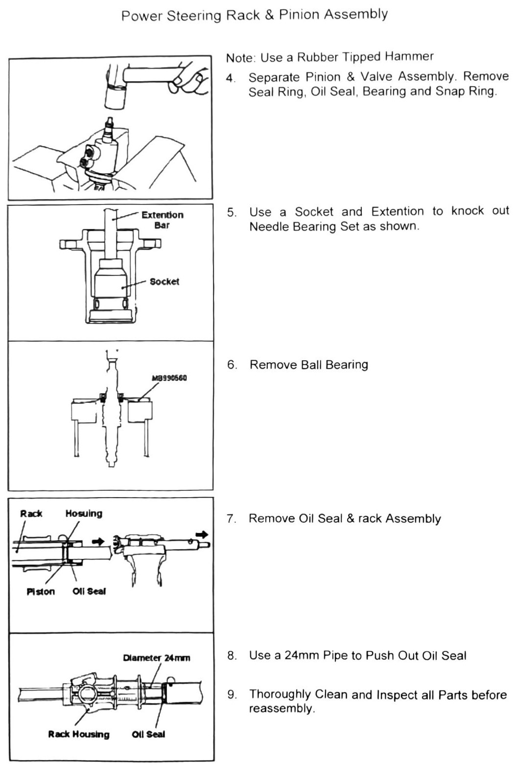
- Separate pinion & valve assembly. Remove seal ring, oil seal, bearing, and snap ring. Use a rubber-tipped hammer.
- Use a socket and extension to knock out the needle bearing set, as shown.
- Remove ball bearing (tool MB990660).
- Remove oil seal & rack assembly (piston oil seal diameter: 24mm (0.945 in)).
- Use a 24mm (0.945 in) pipe to push out the oil seal.
- Thoroughly clean and inspect all parts before reassembly.
Overhaul — reassembly (printed p.301-303)
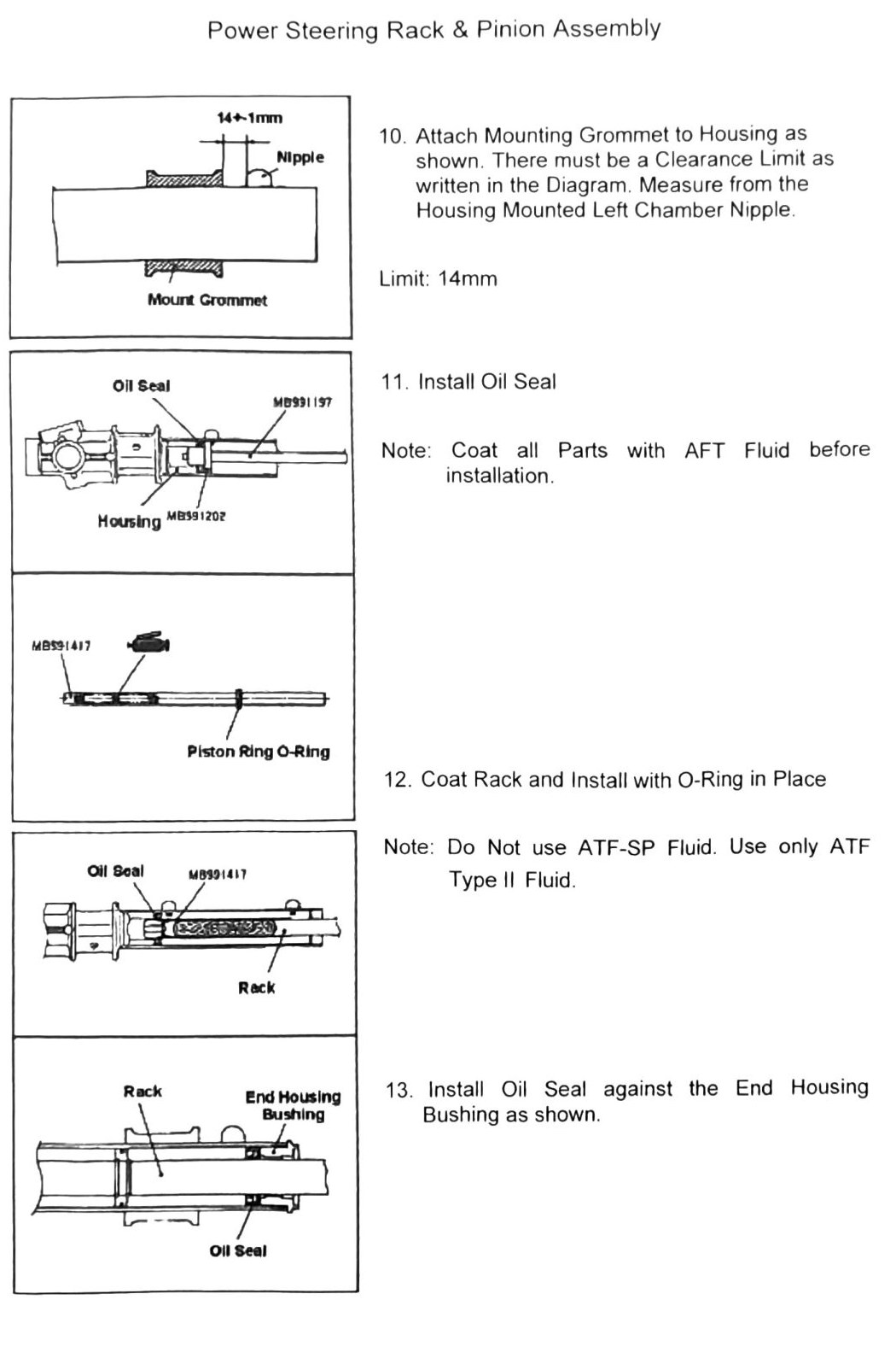
- Attach mounting grommet to housing as shown. There must be a clearance limit as shown in the diagram, measured from the housing-mounted left chamber nipple. Limit: 14mm (0.551 in) (diagram shows “14±1mm (0.551±0.039 in)” at the nipple).
- Install oil seal (tool MB991197). Coat all parts with ATF fluid before installation — do not use ATF-SP fluid, use only ATF Type II.
- Coat rack and install with O-ring in place (tools for piston ring / O-ring: printed as “MB391202” / “MB531417” — these don’t match the MB99xxxx prefix pattern used by every other tool in this chapter and are likely OCR digit errors, plausibly MB991202 / MB991417. (verify printed p.301) before ordering).
- Install oil seal against the end housing bushing, as shown.
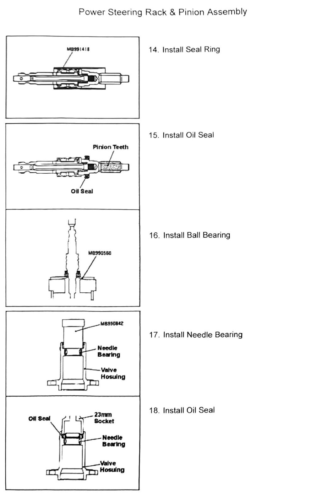
- Install seal ring (tool MB991418).
- Install oil seal (near pinion teeth) — tool part number illegible in scan. (verify printed p.302)
- Install ball bearing — tool part number illegible in scan (printed as “MB930560”, inconsistent with the MB99xxxx pattern). (verify printed p.302)
- Install needle bearing (into valve housing).
- Install oil seal — using a 23mm (0.906 in) socket. Second tool part number illegible in scan (printed as “MB950842”). (verify printed p.302)
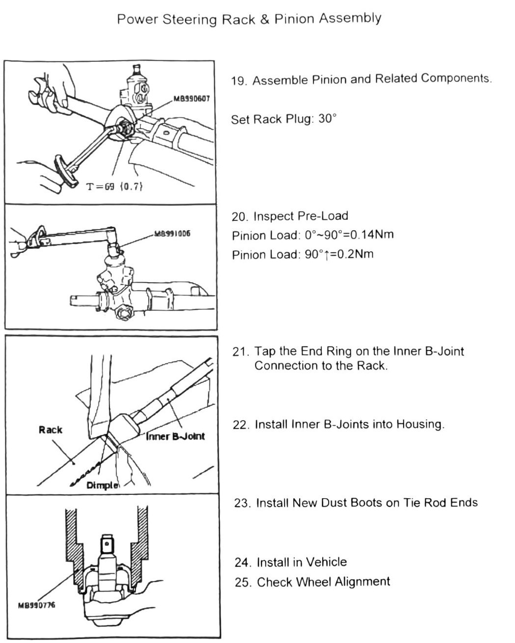
- Assemble pinion and related components (tool MB990607). Set rack plug torque, then set to 30° (preload/back-off angle step — exact tighten-vs-back-off direction not stated in the scan). Torque printed as “T=69 (0.7)”, which is very likely a dropped decimal — the same fastener’s torque is printed correctly as 6.9 N·m (0.7 kgf·m) on printed p.296 of the manual steering procedure. (verify printed p.303) against the physical page before relying on 6.9 N·m.
- Inspect pre-load (tool MB991006):
- Pinion load, 0°-90°: 0.14 N·m (1 in-lb)
- Pinion load, 90°-?: 0.2 N·m (2 in-lb) (upper end of the second range is illegible in the scan — printed as “90°1” — (verify printed p.303))
- Tap the end ring on the inner B-joint connection to the rack (align dimple).
- Install inner B-joints into housing.
- Install new dust boots on tie rod ends (tool MB990776).
- Install in vehicle.
- Check wheel alignment (see Data & Tools).