Manual Steering Rack & Pinion Assembly: Overhaul
Variant note: this section covers the manual (non-power-assisted) steering rack, as distinct from Power Steering Rack & Pinion Assembly. Not confirmed which steering type equips our specific truck (VR-II, 4A30 DOHC turbo, 3A/T, 4WD) — the source pages don’t state a grade/trim-to-steering-type mapping, and it wasn’t established elsewhere in the digitized manual set. Verify by physical inspection (presence/absence of a power steering pump, belt, and fluid reservoir on the engine) or by cross-checking the EPC parts catalog (type code MKPF3) before assuming this section applies. (verify: manual vs. power steering on our truck)
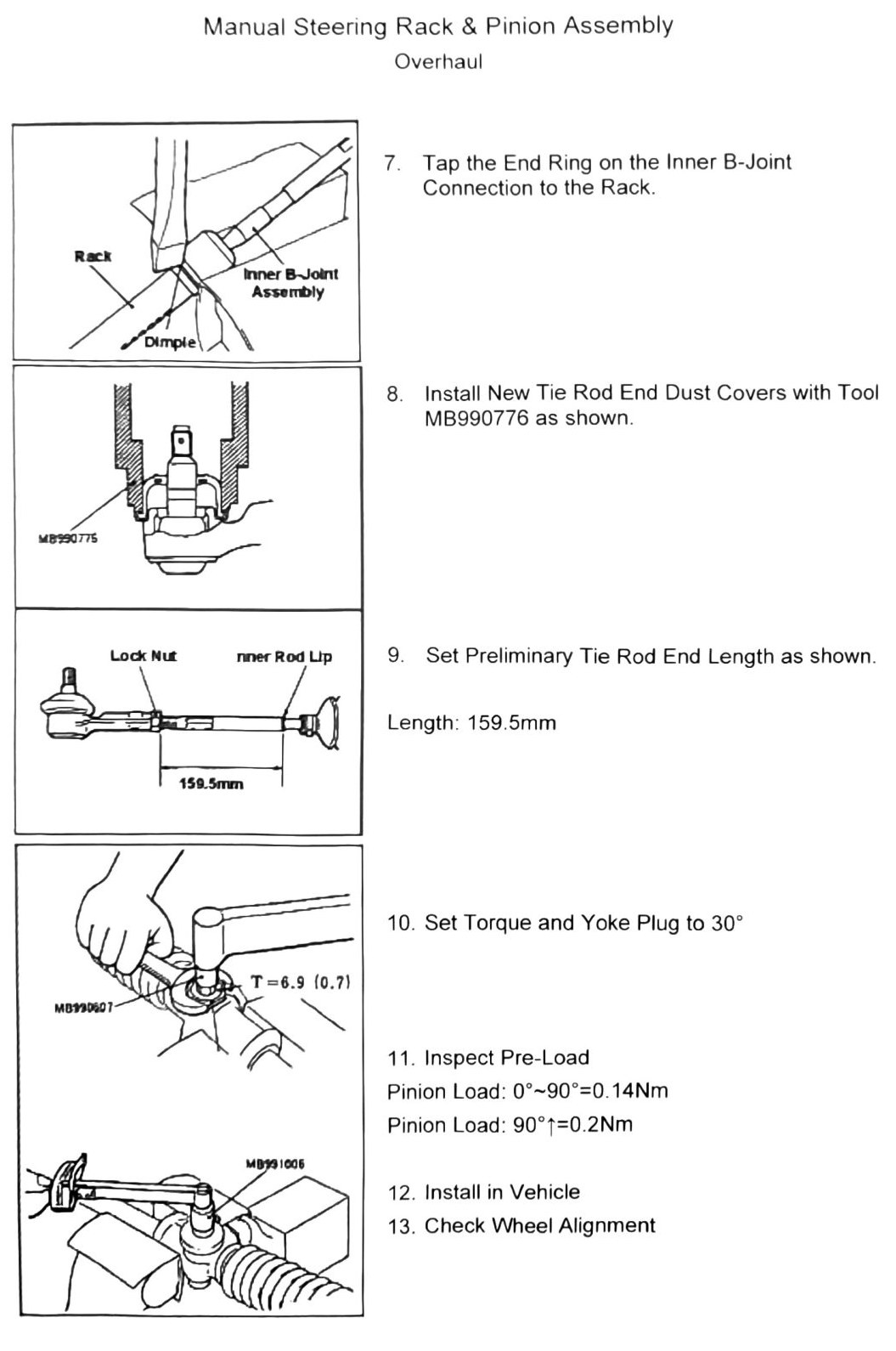
Note (as printed): for hub and driveline components, see Chapter 9.
Removal (printed p.293)
- Remove steering column-to-rack & pinion attachment linkage bolt.
- Remove tie rod split pins and discard — replace with new pins.
- Separate tie rod ends.
- Remove housing brackets.
- Remove rack & pinion assembly.
- Inspect rubber bushings — replace if cracked or oil-soaked.
Torque specifications
| Fastener | Torque |
|---|---|
| Fastener (unlabeled) | 22 N·m (2.2 kgf·m; 16 ft-lb) |
| Fastener (unlabeled, ×2 locations) | 15-33 N·m (1.5-3.4 kgf·m; 11-24 ft-lb) |
| Fastener (unlabeled) | 34 N·m (3.5 kgf·m; 25 ft-lb) |
OCR note: four torque callouts appear on the printed diagram; which specific bolt (column linkage, housing bracket, etc.) each applies to is not legible. (verify printed p.293)
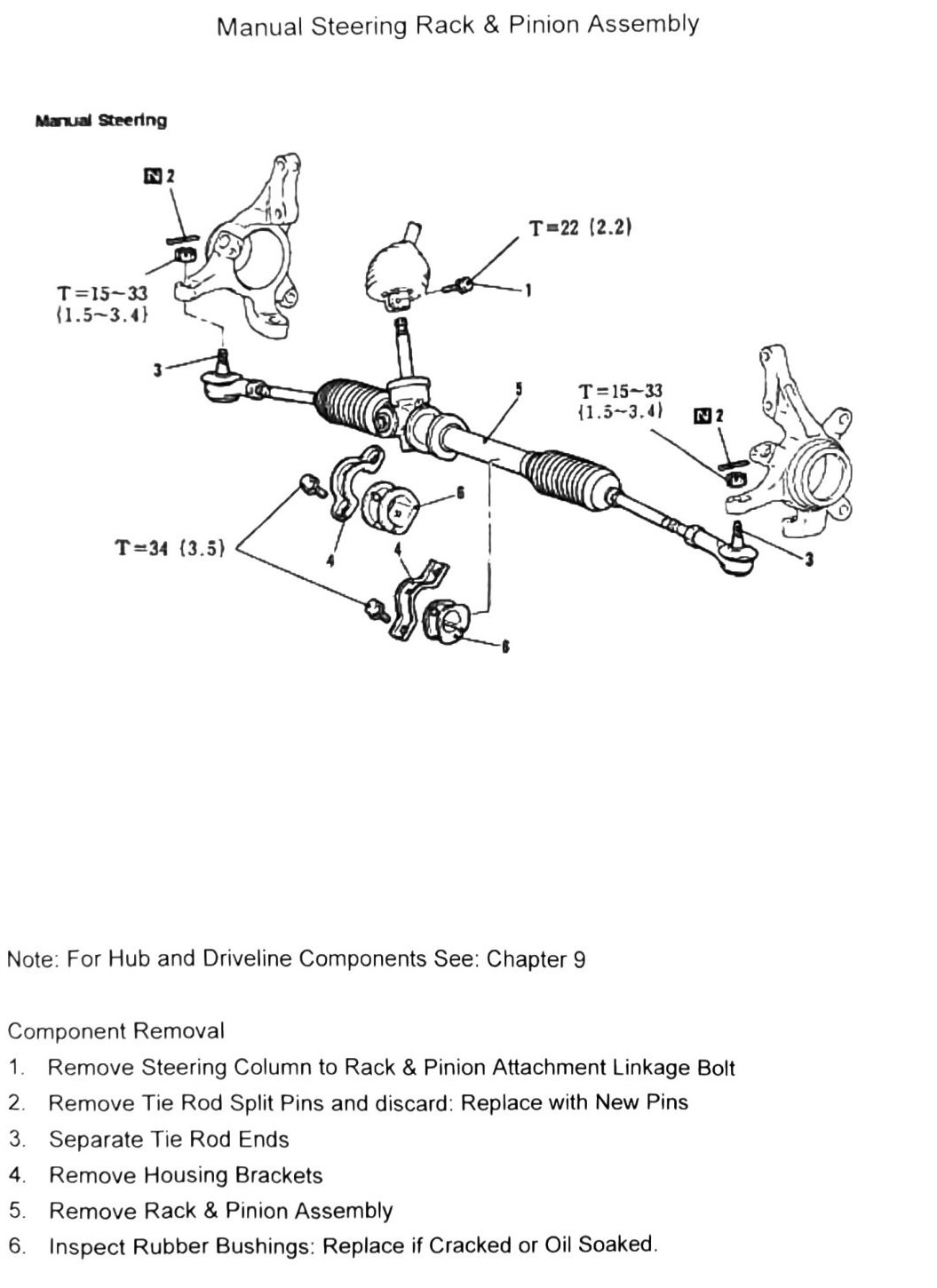
Disassembly components (printed p.294)
| # | Component |
|---|---|
| 1 | Tie Rod Ends |
| 2 | Dust Boots |
| 3 | Clip |
| 4 | Tie Band |
| 5 | Bellows |
| 6 | Tie Rod Inner B-Joint Assembly |
| 7 | Lock Nut |
| 8 | Yoke Plug |
| 9 | Yoke Spring |
| 10 | Support Yoke |
| 11 | Dust Cover |
| 12 | Shaft Seal |
| 13 | Snap Ring |
| 14 | Pinion Bearing Assembly |
| 15 | Rack |
| 16 | Rack Housing |
Torque specifications
| Fastener | Torque |
|---|---|
| Fastener (unlabeled) | 39 N·m (4.0 kgf·m; 29 ft-lb) |
| Fastener (unlabeled, ×2 locations) | 88 N·m (9.0 kgf·m; 65 ft-lb) |
| Fastener (unlabeled, ×2 locations) | 34 N·m (3.5 kgf·m; 25 ft-lb) |
OCR note: fastener assignment for the above torque values is not legible from the scan. (verify printed p.294)
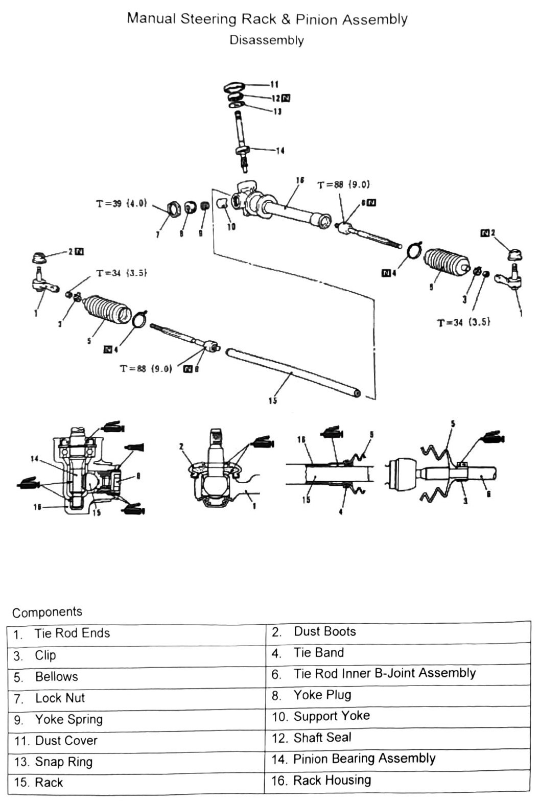
Overhaul — disassembly (printed p.295)
- Place rack housing in a vise as shown. Do not over-tighten — housing damage may occur.
- Remove yoke plug and lock nut (tool MB990607).
- Slide out rack unit.
- Clean and inspect all components.
- With the pinion placed in the housing as shown, use a dial gauge to inspect pinion runout clearance. Limit: below 0.1mm (0.004 in).
- Install shaft seal.
Rack bushing installation note: do not over-grease the internal bushing area — there must be sufficient clearance for the air passage.
Shim sizes are color-coded:
| Color | Thickness |
|---|---|
| Yellow | 1.35mm (0.053 in) |
| Brown | 1.41mm (0.056 in) |
| White | 1.46mm (0.057 in) |
| Blue | 1.52mm (0.060 in) |
| (No color) | 1.57mm (0.062 in) |
See the parts catalogue for further shim-selection detail.
OCR note: the shim-selection tool part number printed on this page was illegible (rendered as garbage characters in the scan). (verify printed p.295)
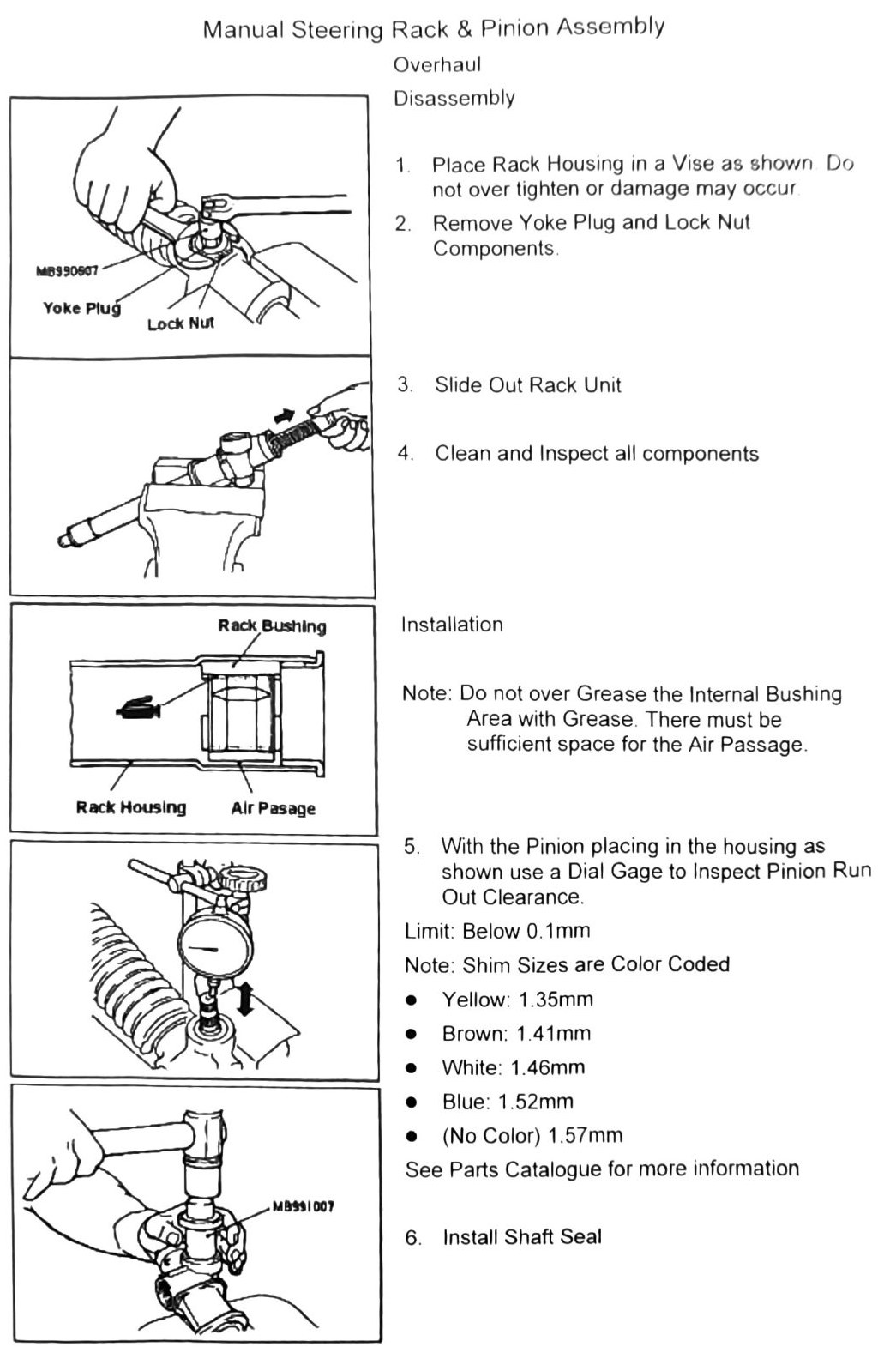
Overhaul — reassembly (printed p.296)
- Tap the end ring on the inner B-joint connection to the rack (align dimple).
- Install new tie rod end dust covers using tool MB990776.
- Set preliminary tie rod end length. Length: 159.5mm (6.28 in).
- Lock nut torque: 6.9 N·m (0.7 kgf·m; 61 in-lb).
- Set yoke plug torque, then set to 30° (preload/back-off angle step — exact tighten-vs-back-off direction not stated in the scan). (verify printed p.296)
- Inspect pre-load:
- Pinion load, 0°-90°: 0.14 N·m (1 in-lb)
- Pinion load, 90°-? : 0.2 N·m (2 in-lb) (upper end of the second range is illegible in the scan — printed as “90°1” — (verify printed p.296))
- Install in vehicle.
- Check wheel alignment (see Data & Tools).