Differential Carrier Overhaul
Rear differential carrier — covers both the standard (“Normal”) carrier and the LSD carrier variant, shown side by side in the source diagrams. See LSD Components for the LSD clutch pack detail.
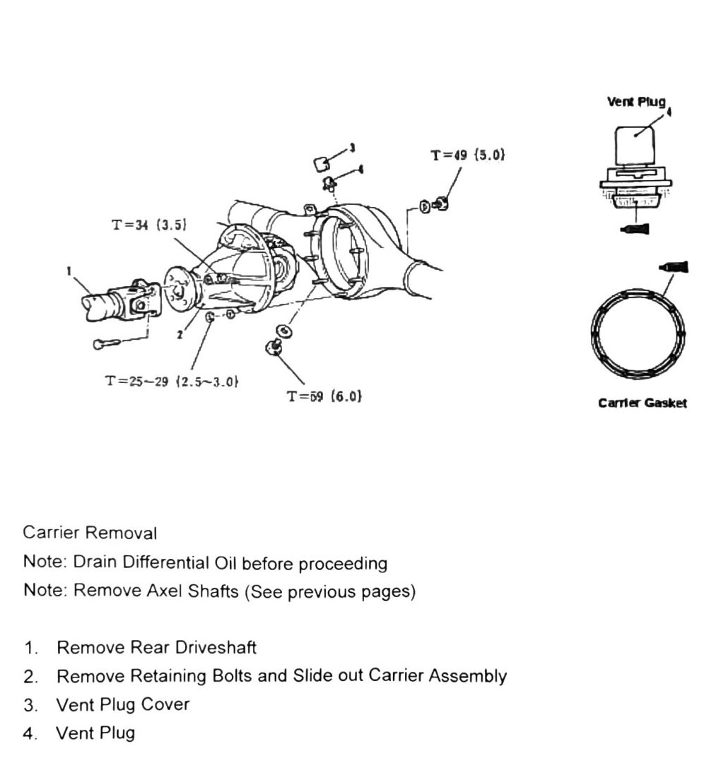
Carrier removal
Note: drain differential oil before proceeding. Remove axle shafts first — see Axel Shaft.
- Remove rear driveshaft.
- Remove retaining bolts and slide out carrier assembly.
- Vent plug cover.
- Vent plug.
Fastener torques
| Torque | Nm (kgf·m) |
|---|---|
| T = 25–29 | (2.5–3.0; 18–21 ft-lb) |
| T = 34 | (3.5; 25 ft-lb) |
| T = 49 | (5.0; 36 ft-lb) |
| T = 59 | (6.0; 44 ft-lb) |
Carrier gasket is replaced at reassembly.
Carrier components (Normal vs. LSD)
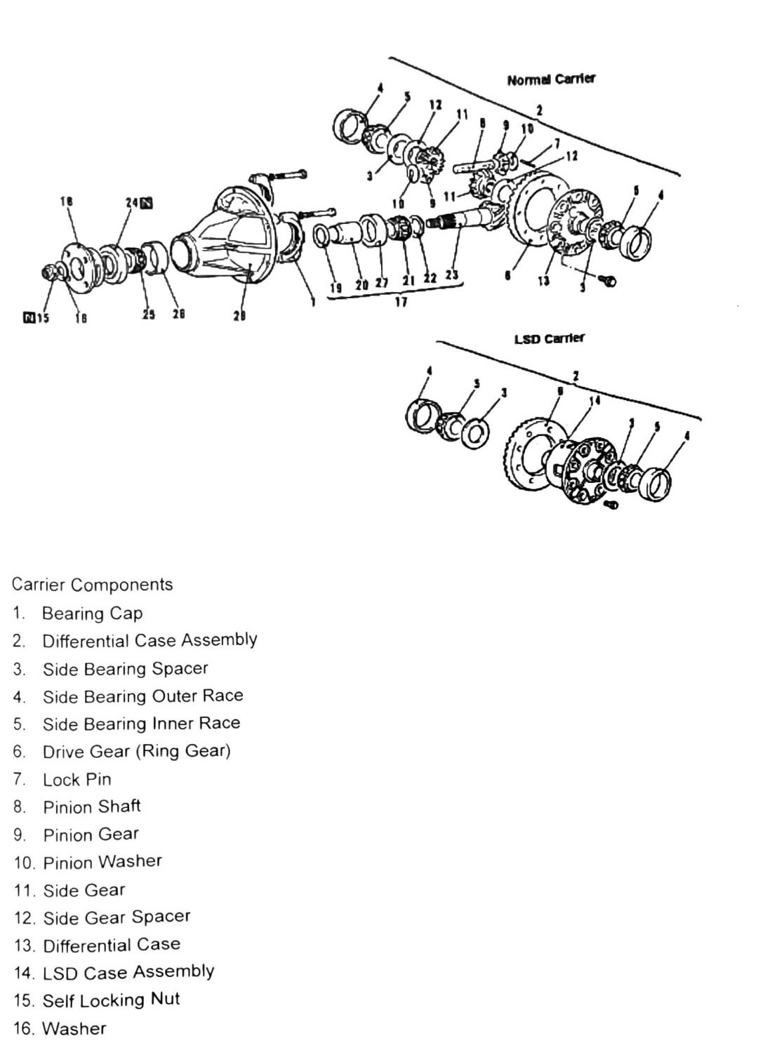
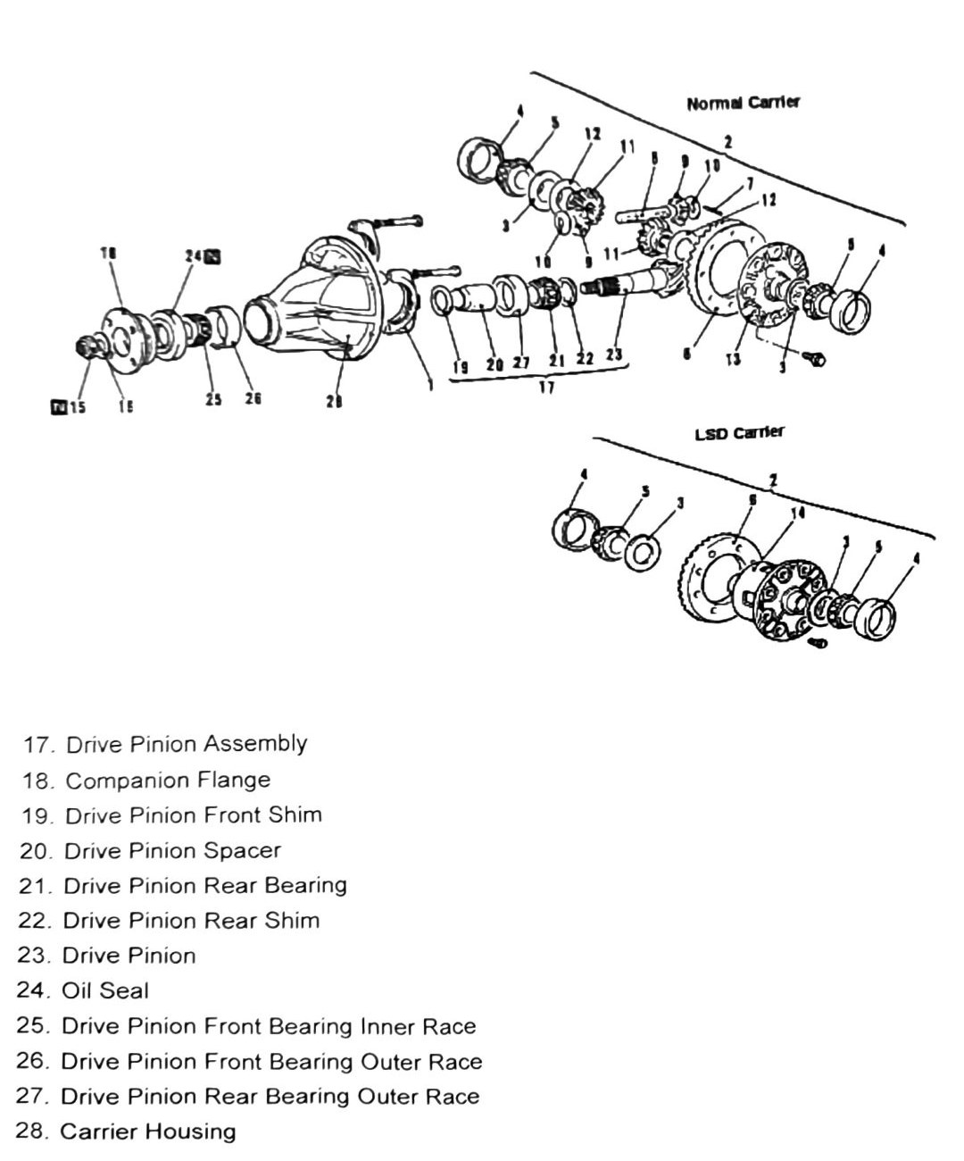
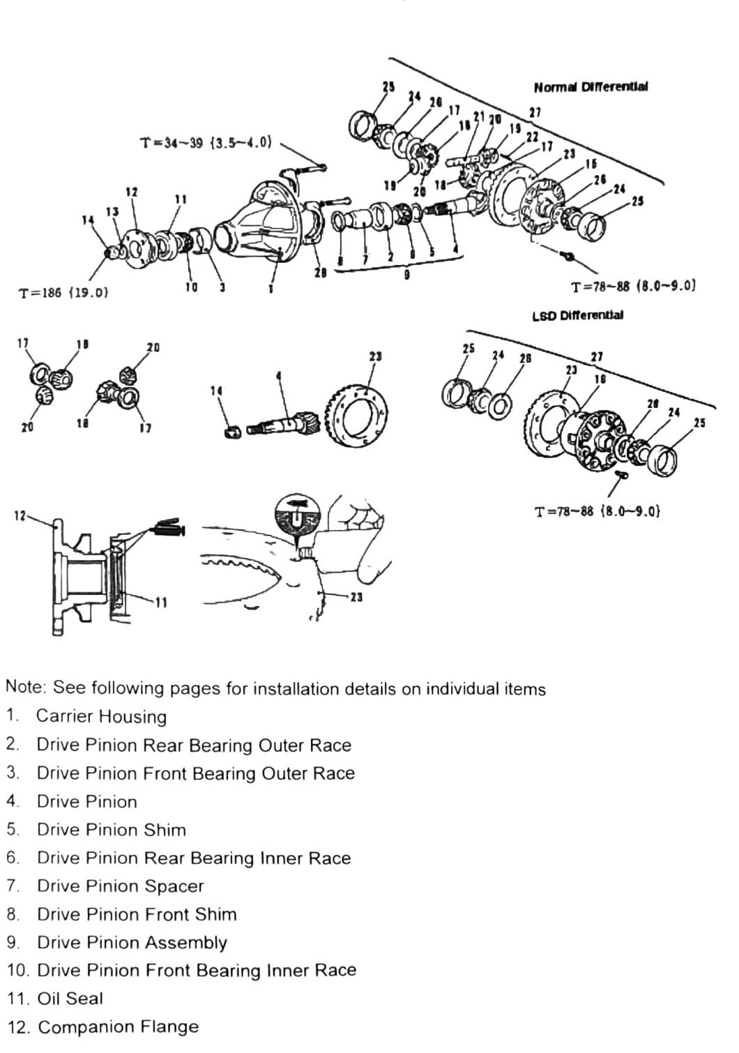
The source shows Normal Carrier and LSD Carrier component diagrams side by side, sharing a single numbered parts list:
- Bearing Cap
- Differential Case Assembly
- Side Bearing Spacer
- Side Bearing Outer Race
- Side Bearing Inner Race
- Drive Gear (Ring Gear)
- Lock Pin
- Pinion Shaft
- Pinion Gear
- Pinion Washer
- Side Gear
- Side Gear Spacer
- Differential Case
- LSD Case Assembly (LSD carrier only)
- Self Locking Nut
- Washer
- Drive Pinion Assembly
- Companion Flange
- Drive Pinion Front Shim
- Drive Pinion Spacer
- Drive Pinion Rear Bearing
- Drive Pinion Rear Shim
- Drive Pinion
- Oil Seal
- Drive Pinion Front Bearing Inner Race
- Drive Pinion Front Bearing Outer Race
- Drive Pinion Rear Bearing Outer Race
- Carrier Housing
Carrier disassembly
- Remove bearing caps.
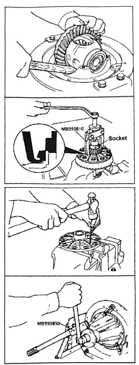
- Pry out carrier with a wood handle as shown. Do not use a metal pry bar.
- Remove side gear bearing and inner race (tool MB990810 with a socket).
- Remove lock pin.
- Remove self-locking nut.
- Remove pinion assembly from the rear of the case (tool MB990850).
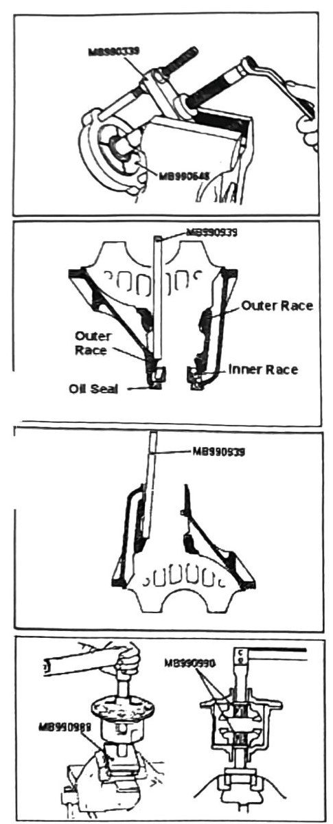
- Remove drive pinion rear gear inner race (tools printed as “MB980339”/“MB990339” — (verify printed p.242, digit illegible) — and MB990645).
- Use tool MB990939 or similar drift punch to remove oil seal and inner & outer races.
- Reverse case to remove rear bearing races (tools printed as MB990990/MB990988 — (verify printed p.242)).
LSD torque engagement test (LSD differential only)
Note: use a torque wrench as shown and test for engagement torque. Once the plates engage, check reading.
| Clutch plate condition | Engagement reading |
|---|---|
| New clutch plates | 29–44 Nm (21–32 ft-lb) |
| Previously-used plates | 10–44 Nm (7.4–32 ft-lb) |
Note: if clutch plates fail, replace and retest. See parts catalogue for thickness options. Full clutch-pack component breakdown: LSD Components.
Disassembly complete.
Assembly
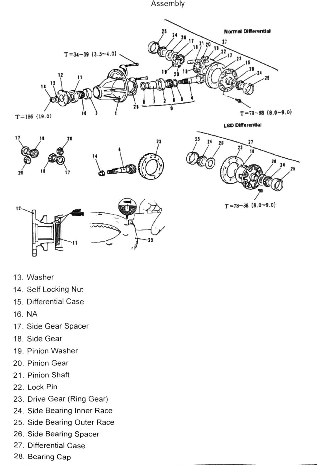
Assembly component numbering (as printed — differs from the disassembly-section numbering above):
- Carrier Housing
- Drive Pinion Rear Bearing Outer Race
- Drive Pinion Front Bearing Outer Race
- Drive Pinion
- Drive Pinion Shim
- Drive Pinion Rear Bearing Inner Race
- Drive Pinion Spacer
- Drive Pinion Front Shim
- Drive Pinion Assembly
- Drive Pinion Front Bearing Inner Race
- Oil Seal
- Companion Flange
- Washer
- Self Locking Nut
- Differential Case
- (not applicable — no part printed for this number in the source)
- Side Gear Spacer
- Side Gear
- Pinion Washer
- Pinion Gear
- Pinion Shaft
- Lock Pin
- Drive Gear (Ring Gear)
- Side Bearing Inner Race
- Side Bearing Outer Race
- Side Bearing Spacer
- Differential Case
- Bearing Cap
Fastener torques (Normal Differential / LSD Differential, as printed)
| Torque | Nm (kgf·m) |
|---|---|
| T = 34–39 | (3.5–4.0; 25–29 ft-lb) |
| T = 78–88 | (8.0–9.0; 58–65 ft-lb) |
| T = 186 | (19.0; 137 ft-lb) |
Note: see following pages for installation details on individual items.
Installation steps
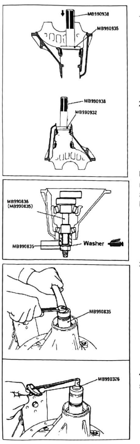
- Install drive pinion rear bearing outer race.
- Reverse case and install drive pinion front bearing outer race.
Drive pinion height inspection: use Drive Pinion Adapter Tool MB991022 and Spacer MB991350 to properly seat bearing and race combination.
- Tighten locknut as shown (tools printed as “MB990835”/“MB990B3S” and MB990326).
- Torque to 0.9–1.20 Nm (9.0–12.0 kgf·cm).
- Rotate assembly and inspect for binding. If free rotation is confirmed, continue with assembly. After the test is complete, remove tool MB991022 and spacer MB991350.
(verify printed p.245) — this 0.9-1.20 Nm reading is unusually low for a locknut torque; it mirrors a similarly low reading on the front differential carrier procedure (Front Differential Carrier Overhaul, 0.98-1.28 Nm) — likely a bearing-preload/seating check rather than final locknut torque, but confirm units against a clean copy.
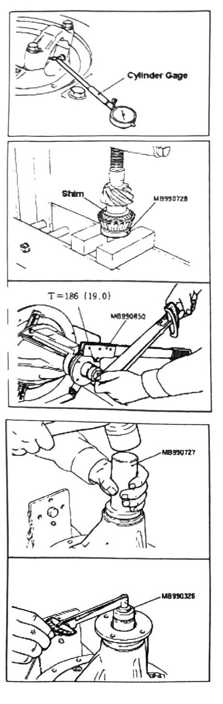
- Use a cylinder gauge to verify diameter. Formula printed as: F = A + B + C − ½D − 86.00 — (verify printed p.246), the formula’s exact term arrangement and units were not fully clean in the scan.
- Press drive pinion rear bearing & shim as shown (tools printed as “MB930728”/MB990728, and “M0890654” — (verify printed p.246, illegible)).
Torque: 186 Nm (19.0 kgf·m; 137 ft-lb).
Note: do NOT install oil seal at this stage.
- Assemble pinion and flange into carrier case and torque as listed. Turn rotating assembly during torque setting. Inspect for binding issues. If no binding persists, remove self-locking nut, flange and pinion.
- Coat new oil seal with axle grease and install as shown (tool MB990727). After oil seal installation is complete, assemble pinion and flange units.
- Set final torque: 0.9–1.20 Nm (9.0–12.0 kgf·cm) (tool MB990326).
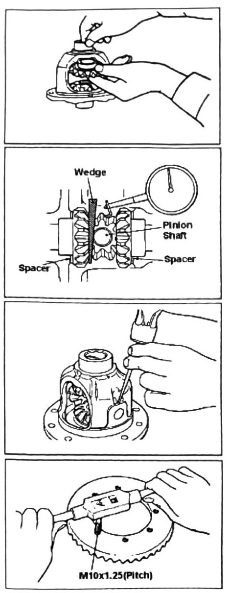
- Assemble differential gears for backlash measurement.
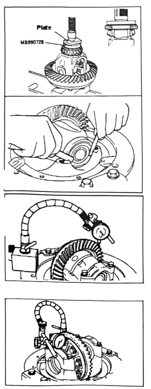
- Place a wedge as shown to stop rotating assembly during the test. Use a dial gauge as shown.
Backlash limit: 0–0.076 mm (0–0.003 in). Note printed: “Replace Pinion @ 0.2mm+” — (verify printed p.247), exact meaning unclear from OCR; likely indicates the pinion/shim set should be replaced if backlash exceeds roughly 0.2 mm, but confirm before relying on it.
- Install lock pin.
- Tap all drive gear (ring gear) holes before installation, to remove residue from previous thread lock applications.
- Add thread lock sealant and attach to rotating assembly carrier. Bolt size: M10 × 1.25 (pitch).
Note: when pressing side bearing inner race, use a flat plate (tool MB990728) as shown, so as not to cause damage to the race and assembly.
- Press side gear inner bearing race. Load assembly into carrier.
- Inspect side clearance.
Limit: 0.05 mm (0.002 in).
Note: maximum two (2) shims may be used at one time. See parts catalogue for shim size options.
- Inspect drive gear (ring gear) run out.
Limit: 0.10–0.15 mm (0.004–0.006 in).
- Inspect differential rotating case run out.
Limit: 0.05 mm (0.002 in).
Note: if all clearances are met, reassemble remaining components and install in vehicle. See previous sections for detailed instructions on complete assembly.