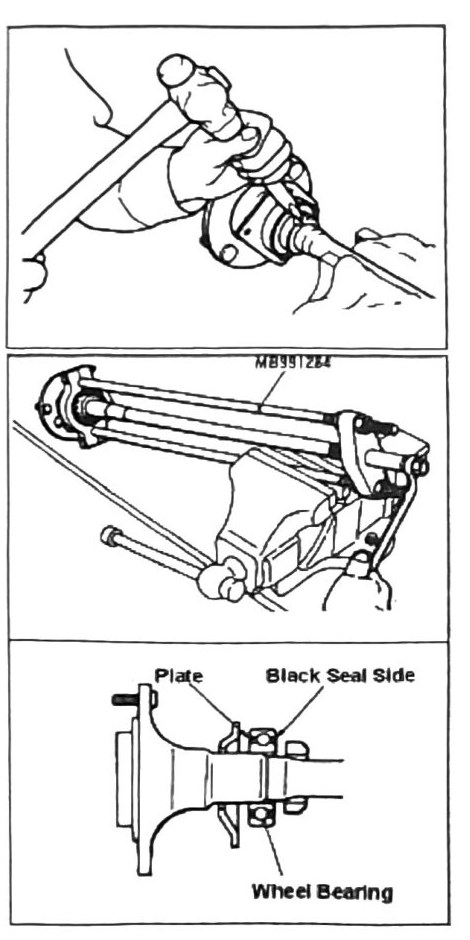
Axel Shaft
Components
- Brake Drum
- Rear Brake Solid Line
- Brake Shoes
- Parking Brake Cable
- Rear Speed Sensor (ABS vehicle)
- O-Ring (ABS vehicle)
- Rubber Plug
- Axel Shaft Assembly
- Packing (Gasket)
- Shim
- Packing (Gasket)
- Oil Seal
Fastener torques
| Torque | Nm (kgf·m) |
|---|---|
| T = 15 | (1.5; 133 in-lb) |
| T = 29 | (3.0; 21 ft-lb) |
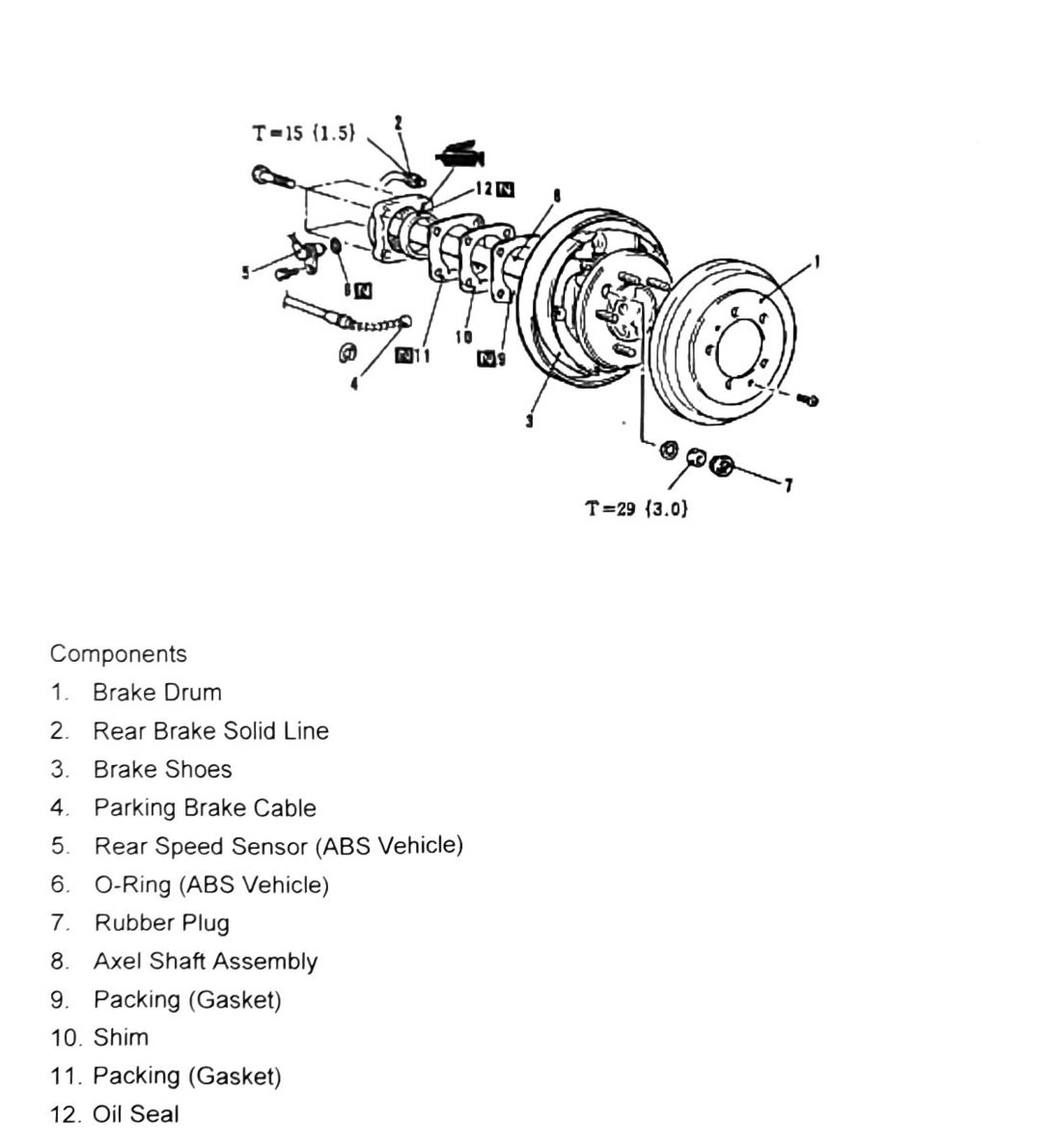
Axle housing oil seal replacement
- Raise rear of vehicle and support.
- Remove tire and brake drum.
- Remove axle shaft — see Axle Shaft Removal above.
- Use slide hammer and lip adapter (tools MB990211, MB990241, MB990212) to remove oil seal.
- Coat new seal with axle grease and install as shown (tools MB990935, MB990938).
Note: for more details see the following pages of this section.
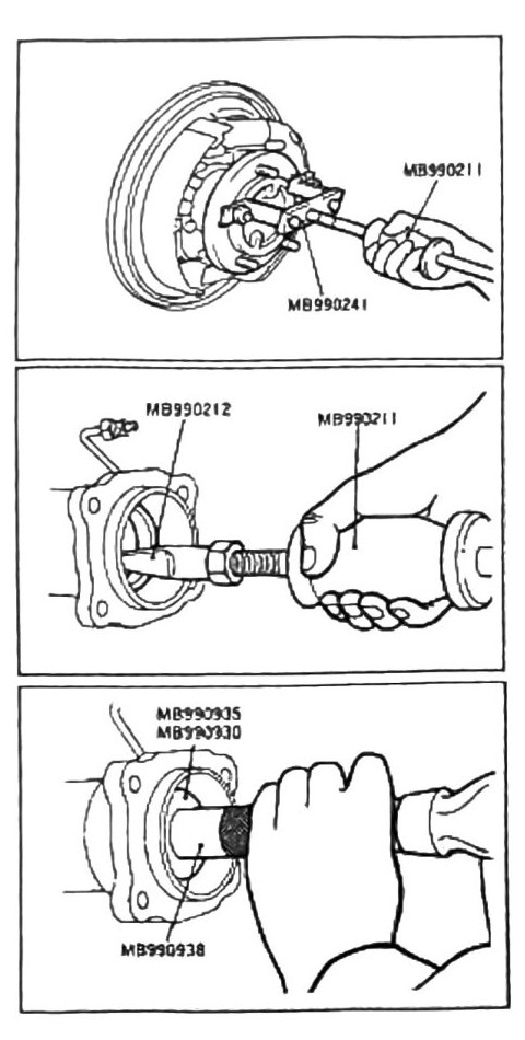
Rotor pickup gear removal (ABS vehicle)
Components
- Rotor Pickup (ABS)
- Bearing Inner Retainer
- Wheel Bearing
- Bearing Outer Retainer
- Axel Shaft
Procedure
- Use tool MB990560 adapter to stabilize axle shaft.
- Press off pickup gear.
- Use a grinder to split inner retainer as shown.
Caution: grind approximately 1-1.5 mm (0.039–0.059 in) and split retainer.
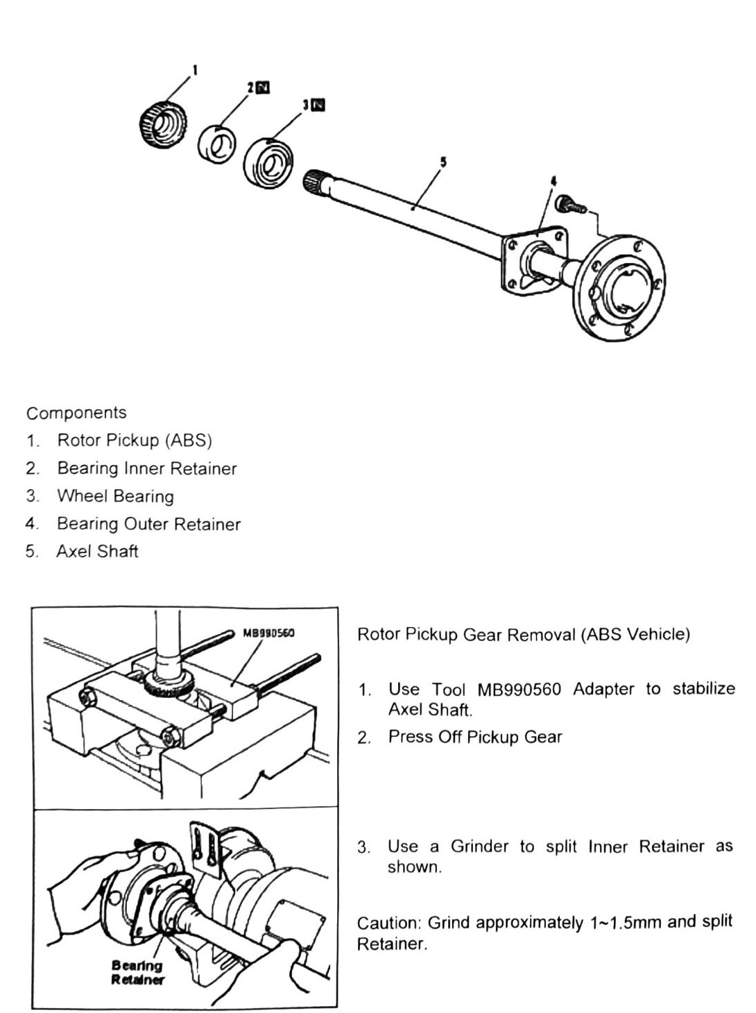
- Remove remaining inner retainer with a punch as shown.
- Remove wheel bearing with a wheel bearing puller (tool MB991284) as shown.
Note: once removed, wheel bearings cannot be reused.
- Install bearing and components in reverse order.
Note: wheel bearing must be facing the correct direction for installation. The “Black” colored side must face inward toward the carrier. The plate side faces toward the drum.