Front Differential Carrier Overhaul (4WD)
Note: see previous pages in this chapter for related component removal. Drain carrier oil before disassembly.
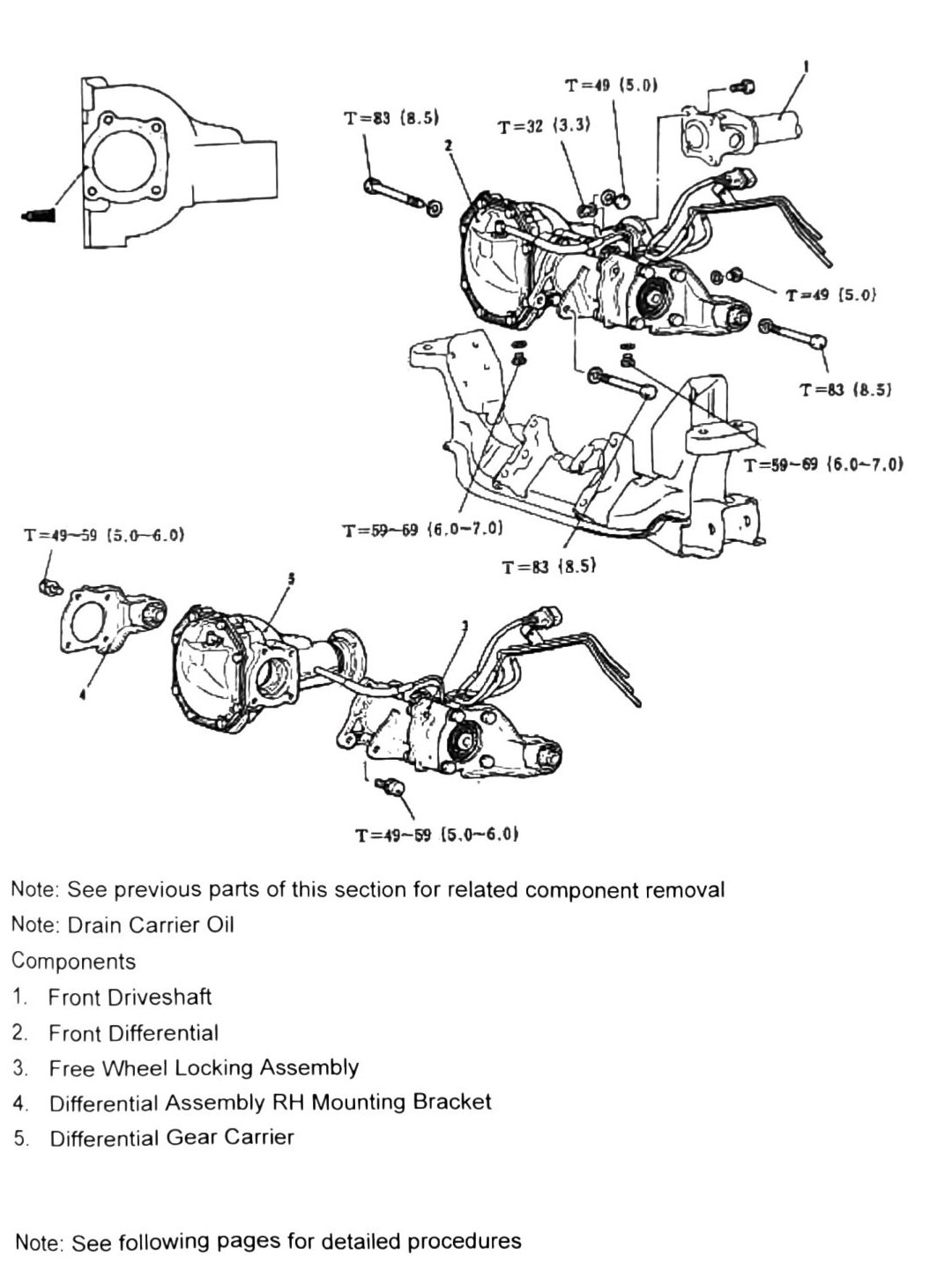
Components (assembly overview)
- Front Driveshaft
- Front Differential / Differential Assembly RH (verify printed p.213 — item 2’s label combined two phrases in the scan; likely two separate callouts on the diagram)
- Free Wheel Locking Assembly
- Mounting Bracket
- Differential Gear Carrier
Fastener torques
| Torque | Nm (kgf·m) |
|---|---|
| T = 32 | (3.3; 24 ft-lb) |
| T = 49 | (5.0; 36 ft-lb) |
| T = 83 | (8.5; 61 ft-lb) |
| T = 49–59 | (5.0–6.0; 36–44 ft-lb) |
| T = 59–69 | (6.0–7.0; 44–51 ft-lb) |
Note: see following pages for detailed procedures.
Carrier backlash inspection
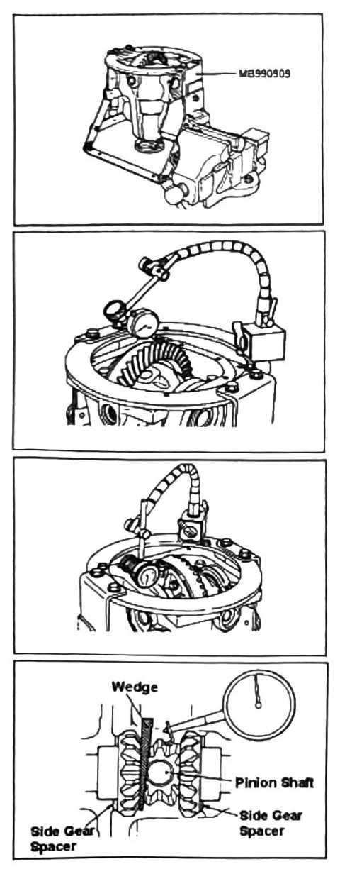
- Place carrier unit in a cradle such as MB990909. Remove rear cover.
- Attach a dial gauge as shown. Rotate carrier assembly and check backlash.
Limit: 0.05 mm (0.002 in).
Drive gear run out inspection
- Attach a dial gauge as shown and inspect run out clearance.
Limit: 0.05 mm (0.002 in).
Differential gear static backlash
- Place a wedge as shown to hold side gears in place. Attach a dial gauge as shown.
Limit: 0.05–0.15 mm (0.002–0.006 in).
Note: if over limit, replace pinion shaft and retest.
Carrier components
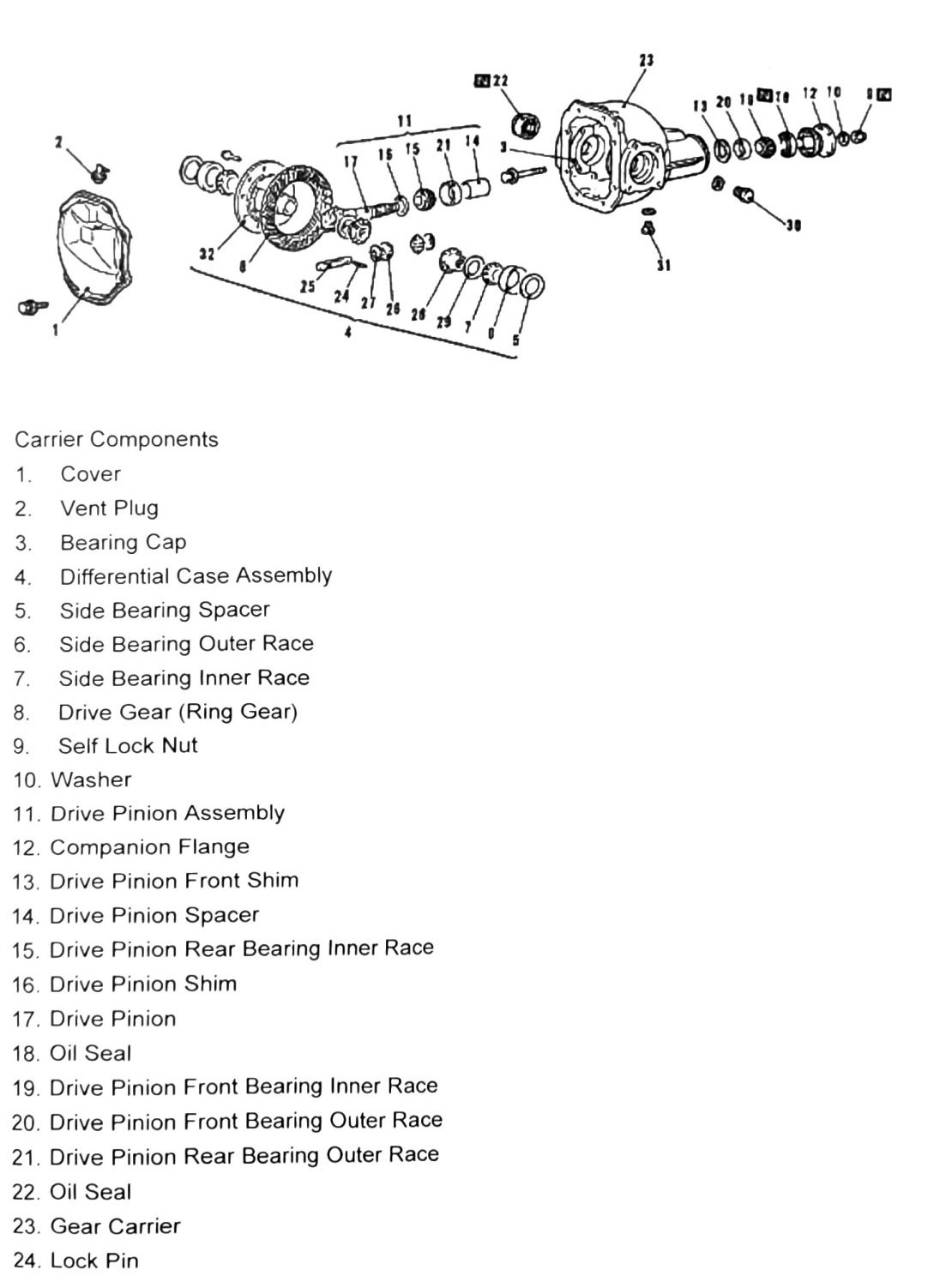
- Cover
- Vent Plug
- Bearing Cap
- Differential Case Assembly
- Side Bearing Spacer
- Side Bearing Outer Race
- Side Bearing Inner Race
- Drive Gear (Ring Gear)
- Self Lock Nut
- Washer
- Drive Pinion Assembly
- Companion Flange
- Drive Pinion Front Shim
- Drive Pinion Spacer
- Drive Pinion Rear Bearing Inner Race
- Drive Pinion Shim
- Drive Pinion
- Oil Seal
- Drive Pinion Front Bearing Inner Race
- Drive Pinion Front Bearing Outer Race
- Drive Pinion Rear Bearing Outer Race
- Oil Seal
- Gear Carrier
- Lock Pin
Carrier components (continued)
- Pinion Shaft
- Pinion Gear
- Pinion Washer
- Side Gear
- Side Gear Spacer
- Filler Plug (Oil)
- Drain Plug (Oil)
- Differential Case
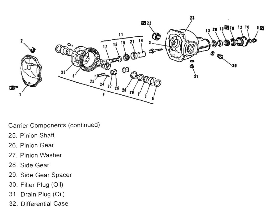
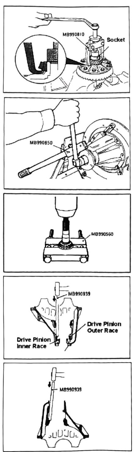
Disassembly
Side bearing inner race removal
- Place a used socket between the gear puller (MB990810) and the race lip as shown.
- Remove race and discard.
Drive gear (pinion) removal
- Use handle MB990850 to retain flange from moving.
- Remove retaining nut and slide gear out from the rear of the case.
Drive pinion rear bearing inner race removal
- Use base MB990560 and press off gear.
Oil seal / drive pinion race set removal
- Use tool MB990939 or similar race removal punch to drive out oil seal, inner & outer races.
Drive pinion rear bearing outer race removal
- Use tool MB990939 or similar race removal punch to drive out outer race as shown.
Disassembly complete.
(verify printed p.217) — one tool number is also printed as “MB990919”; likely an OCR duplicate/misread of MB990939 (same tool referenced three times on this page with two spellings) rather than a distinct tool.
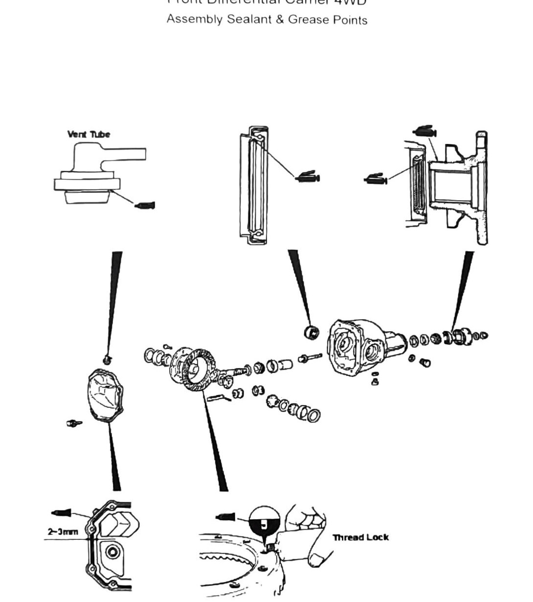
Assembly sealant & grease points
- Vent tube: apply sealant/grease per diagram.
- Thread lock: apply to specified bolts (gap called out as 2-3 mm (0.079–0.118 in) on the diagram).
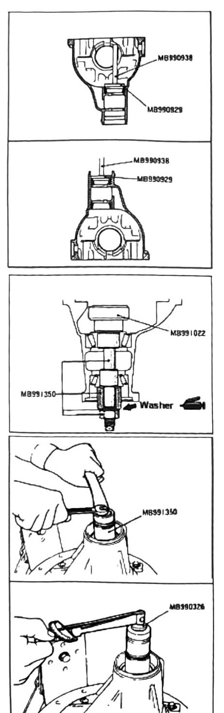
Installation
- Install drive pinion rear bearing outer race as shown.
- Install drive pinion front bearing outer race as shown (tools MB990929, MB990938).
Drive pinion height inspection
Use Drive Pinion Adapter Tool MB991022 and Spacer MB991350 to properly seat bearing and race combination.
- Tighten locknut as shown (tool MB991350).
- Torque to 0.98–1.28 Nm (10.0–13.0 kgf·cm).
- Rotate assembly and inspect for binding. If free rotation is confirmed, continue with assembly.
(verify printed p.219) — the 0.98–1.28 Nm torque reading is unusually low for a pinion-nut-style fastener; confirm units (kgf·cm vs. kgf·m) against a clean copy before use — this may be a locating/seating torque rather than final pinion nut torque.
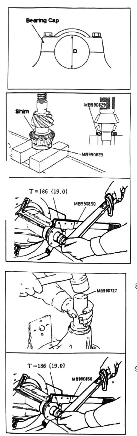
Bearing cap diameter inspection
Formula: E = A + B + C − ½D − 76.0
- Press bearing with drive pinion rear shim in place (tool MB990829).
Torque: 186 Nm (19.0 kgf·m; 137 ft-lb).
- Place unit in carrier without oil seal as shown. Torque to specifications shown in the diagram. Check rotating assembly for free spin. If binding is not detected, remove flange and install oil seal.
- Install front carrier oil seal (tool MB990727).
Torque: 186 Nm (19.0 kgf·m; 137 ft-lb).
- Install flange and torque to specifications. Check for free-rotating assembly. If no binding is detected, continue to next step.
- Pinion lock pin installation — use a brass punch and install lock pin as shown.
- Before attaching ring gear, tap all holes before installation.
- Apply thread lock to all retaining bolts. Attach ring gear.
Note: when pressing side bearing inner race, use a flat plate (tool MB990829) as shown, so as not to cause damage to the race and assembly.
- Press side gear inner bearing race.
- Install rotating assembly.
- Measure side clearance.
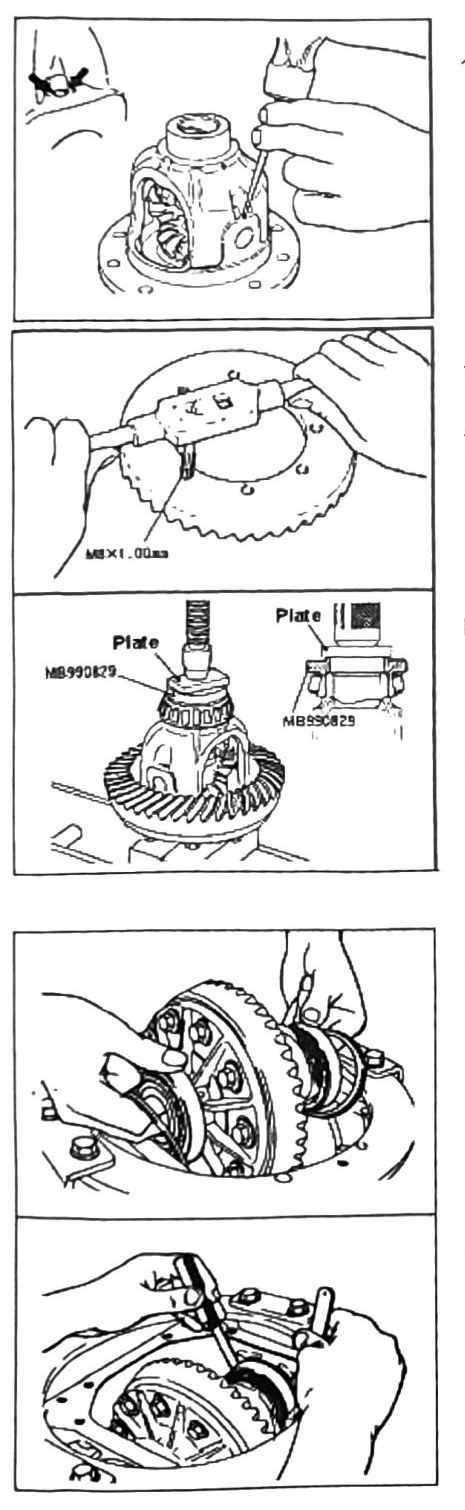
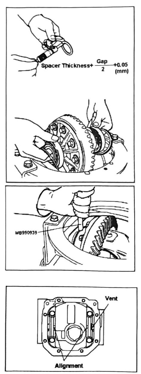
- If backlash is determined to be over specification in the previous step, different shim sizes may be required to meet spec. Use the formula on the diagram (Spacer Thickness + Gap ÷ 2 + 0.05 mm (0.002 in)) to calculate required shims. All available shim sizes are listed in the parts catalogue.
- Assemble carrier rotating assembly with properly sized shims.
- Use a brass punch to seat side bearing outer race if required.
Note: do NOT use a steel-tipped punch — damage will occur.
- Install bearing caps and check for free rotation. Return to the beginning of this section and recheck all backlash specifications. Once all specifications are verified, apply final bearing cap torque and install in vehicle.