A/T Shift Control Assembly
Applies directly to our truck — this is our shifter, in place of the manual-transmission shift control covered in Transmission Shift Control.
A/T-ECU removal
- Disconnect electrical connectors and attachment bolts. Remove ECU.
Shifter assembly removal
- Remove Snap Ring.
- Remove Retaining Clip.
- Disconnect Key Interlock Cable system.
- Disconnect Shift-Lock Cable.
- Disconnect Illumination Power Connector.
- Remove Shifter retaining bolts, remove Shifter Assembly.
Cable removal components
- Clip
- Plate Assembly
- Split Pin
- Clip
- Shifter Cable
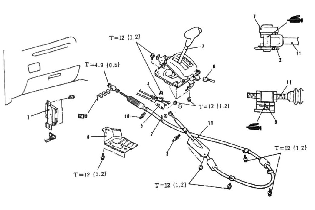
Torque
| Torque callout | N·m (kgf·m) |
|---|---|
| T=12 (106 in-lb) | (1.2) |
| T=12 (106 in-lb) | (1.2) |
| T=12 (106 in-lb) | (1.2) |
| T=12 (106 in-lb) | (1.2) |
| T=4.9 (43 in-lb) | (0.5) |
(verify printed p.185) — the diagram shows five torque callouts, four of them the same T=12 (1.2) value plus one T=4.9 (0.5). Which fastener gets the lower 4.9 N·m value is not confirmed from OCR — do not assume without checking the printed diagram.