Transmission Shift Control
This page covers the manual transmission shift linkage and the transfer case shift linkage as two separate assemblies sharing one diagram.
- Transmission Shifter Control (items 1-9 below): manual transmission (5M/T) only — not applicable to our 3A/T. See A/T Shift Control Assembly for our truck’s shifter.
- Transfer Case Control (items 10-20 below): applies directly to our 4WD truck regardless of main transmission type.
Transmission Shifter Control components
- Shift Knob
- Retainer
- Shaft Lever Cover
- Lever Assembly
- Bushing
- Gasket — use sealant
- Stop Plate
- Gasket — use sealant
- Lever (Shaft)
Transfer Case Control components
- Knob
- Lever Assembly
- Retainer
- Boot
- Inner Boot
- Cover
- Control Lever Assembly
- Gasket — apply sealant
- Stopper Plate
- Gasket — apply sealant
- Lever (Shaft)
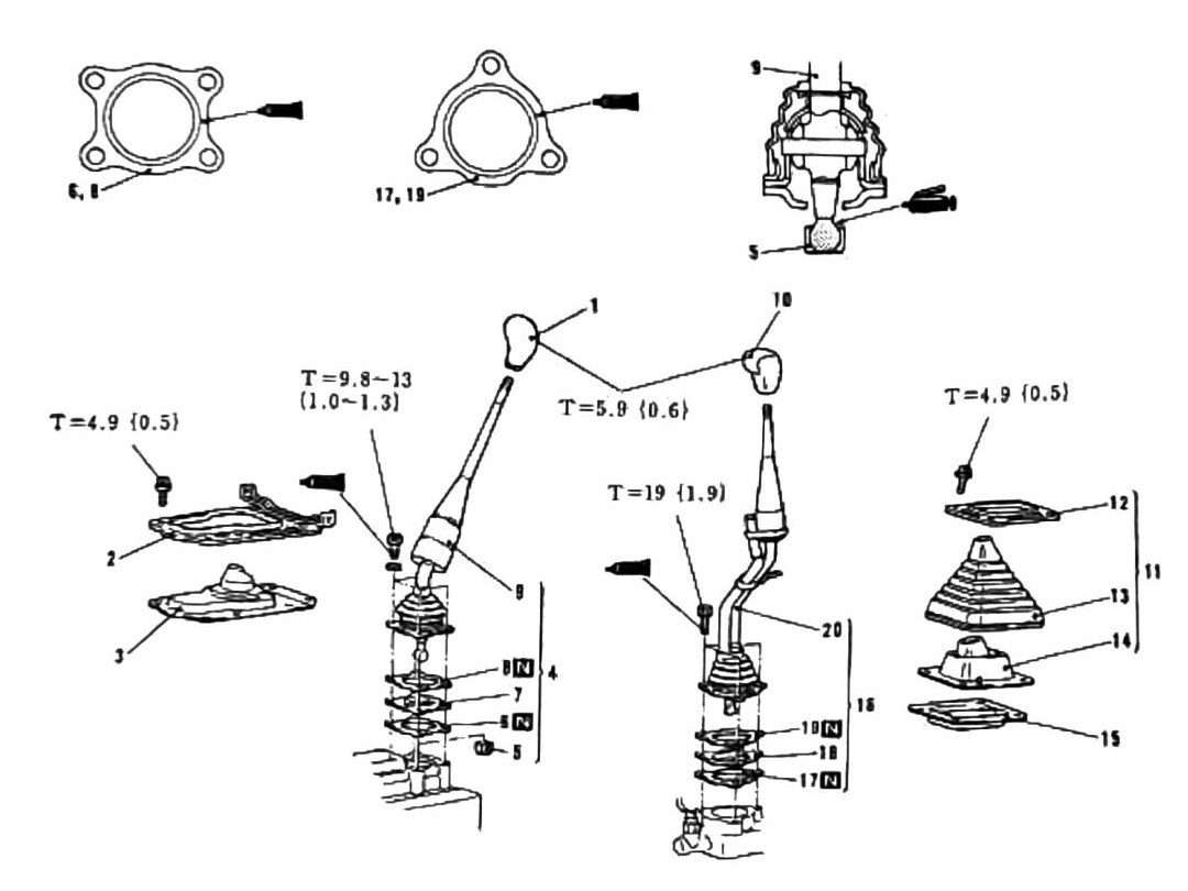
Torque
| Torque callout | N·m (kgf·m) |
|---|---|
| T=9.8-13 (87-115 in-lb) | (1.0-1.3) |
| T=4.9 (43 in-lb) | (0.5) |
| T=5.9 (52 in-lb) | (0.6) |
| T=4.9 (43 in-lb) | (0.5) |
| T=19 (168 in-lb) | (1.9) |
(verify printed p.172) — five torque callouts are legible, but the leader lines tying them to specific fasteners among the 20 components above did not survive OCR. Given the parts involved, T=19 (1.9) most likely corresponds to the larger Lever (Shaft) mounting bolts (items 9/20), and the 4.9-5.9 N·m values most likely correspond to smaller cover/gasket screws — but this attribution is not confirmed and should not be relied on without checking the printed diagram.
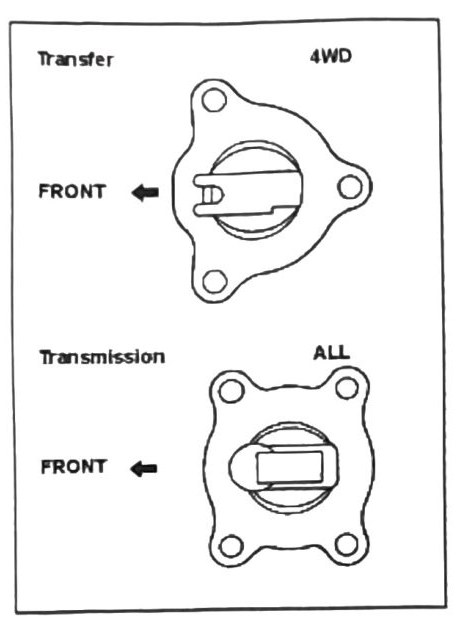
Stopper plate installation
Use the following two diagrams for proper stopper plate installation: Transfer (4WD, FRONT-oriented) and Transmission (ALL, FRONT-oriented).
Note: M8×1.25mm attachment bolts should have thread-lock sealant applied. Failure to apply sealant can cause bolts to back out during vibration.