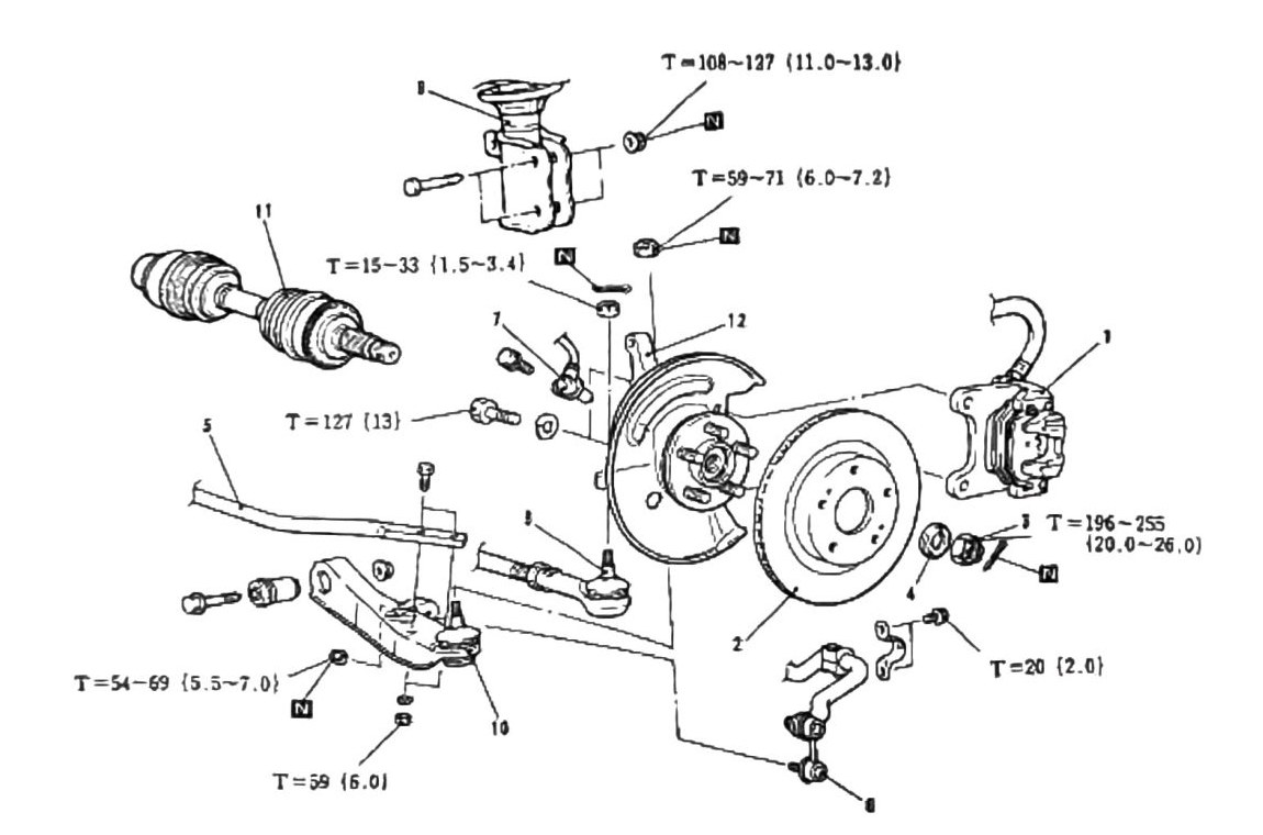
Hub & Knuckle Overhaul (4WD)
Applies to our truck’s front hub/knuckle assemblies (4WD).
Component removal procedure
- Remove brake caliper.
- Remove disk brake rotor.
- Remove split pin and castle nut — discard and replace split pin.
- Remove washer.
- Disconnect strut bar from lower arm.
- Disconnect stabilizer bar.
- Disconnect wheel speed sensor (ABS vehicles).
- Press out lower tie rod end.
- Remove strut-to-knuckle attachment bolts.
- Press out lower arm-to-knuckle joint.
- Remove drive axle.
- Remove hub & knuckle assembly.
- Install in reverse order.
Note: see below for removal & installation key points.
Fastener torques
| Torque, Nm (kgf·m) | Fastener (traced from diagram callout arrows) |
|---|---|
| T = 108–127 (11.0–13.0; 80–94 ft-lb) | Bolt at the strut lower bracket — strut-to-knuckle attachment (step 9) |
| T = 59–71 (6.0–7.2; 44–52 ft-lb) | Nut at the upper strut/knuckle area, just below the 108–127 callout — exact fastener not fully traceable at 150dpi |
| T = 15–33 (1.5–3.4; 11–24 ft-lb) | Small bolt/stud between strut and knuckle (speed-sensor bracket area) — exact fastener not fully traceable at 150dpi |
| T = 54–69 (5.5–7.0; 40–51 ft-lb) | Nut at the forward end of the lower arm — strut bar-to-lower arm attachment (step 5) |
| T = 127 (13.0; 94 ft-lb) | Bolt entering the knuckle from the left, below the sensor area — exact fastener name not traceable at 150dpi |
| T = 20 (2.0; 15 ft-lb) | Bolt on the stabilizer link mounting bracket (step 6 area) |
| T = 59 (6.0; 44 ft-lb) | Nut beneath the lower arm-to-knuckle joint (ball joint stud, step 10) |
| T = 196–255 (20.0–26.0; 145–188 ft-lb) | Hub castle nut (items 3/4) — arrow traced directly to the castle nut |
(verified against scan p.202, 2026-08-30) — callout arrows for the castle nut (196–255), strut-to-knuckle bolt (108–127), strut bar nut (54–69), ball joint nut (59), and stabilizer bracket bolt (20) were visually traced on the scan. Three callouts (59–71, 15–33, 127) have visible leader lines but their target fasteners cannot be conclusively identified at 150dpi — (verify printed p.202 for those three only — re-checked against scan 2026-08-30: leader-line targets illegible at 150dpi, needs the printed book). The castle nut torque also recurs identically on printed p.203, 205, 206, and 207.
Tie rod removal
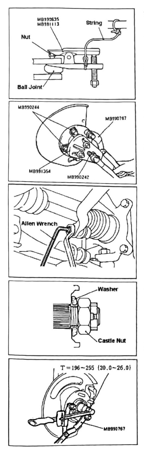
Tools: MB990635 (Linkage Press) and MB991113 (verified against scan p.203, 2026-08-30 — the tie rod removal panel labels the press with two stacked part numbers, MB990635 / MB991113).
- Attach a piece of string as shown to prevent the tie rod press from dropping after removing the tie rod.
- Press out tie rod.
Drive axle removal
Tools: MB991354 (Puller Plate), MB990244 (labeled with arrows to the puller attachment bolts), MB990242 (labeled on the puller shaft/handle), and MB990767 (Hub Placement Holder). (verified against scan p.203, 2026-08-30 — the drive axle removal panel carries both MB990244 and MB990242 as separate labels, so the earlier “one tool, digit illegible” reading was wrong; neither label reads MB990241 on this page.)
- Attach the tools listed in the diagram.
- Press out drive axle.
Note: never use a hammer to knock out shafts — damage will occur.
Stabilizer link removal
- Use a six-sided Allen wrench and a box wrench as shown to remove stabilizer links.
Washer & castle nut alignment
- Use the diagram for proper installation configuration of the washer & castle nut.
- Always use a new split pin during installation.
Castle nut torque
- Use the setup shown for proper torque of the castle nut. Turn the hub frequently during the torque procedure for proper bearing settings.
Torque: 196–255 Nm (20.0–26.0 kgf·m; 145–188 ft-lb).
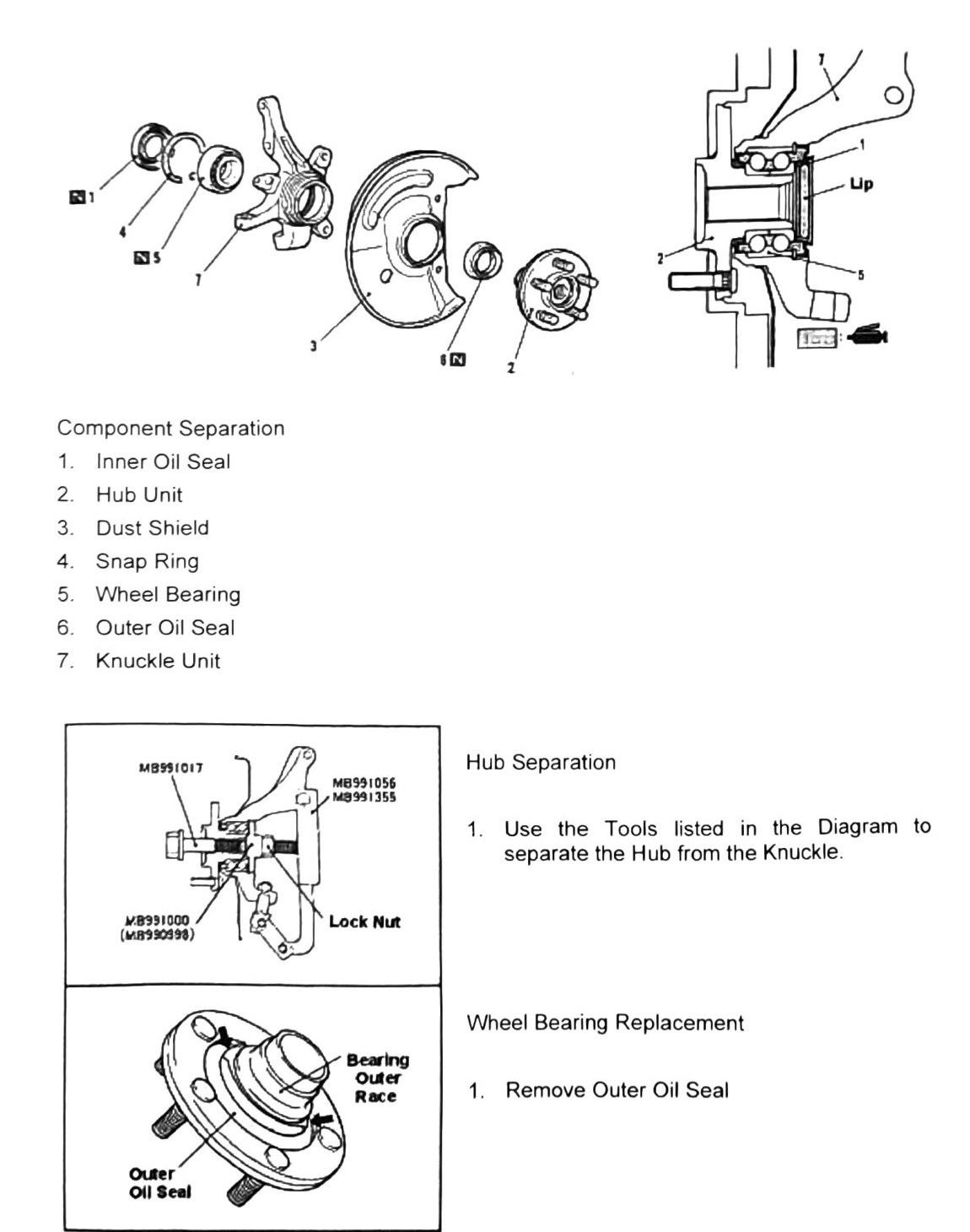
Component separation
- Inner Oil Seal
- Hub Unit
- Dust Shield
- Snap Ring
- Wheel Bearing
- Outer Oil Seal
- Knuckle Unit
Tools: MB991017 (Front Hub Reamer & Installer), MB991056 (Knuckle Arm Bridge Adapter Plate), MB991355 (new tool, no description recovered), MB991000 with MB990998 (Spacer) as an alternate/companion tool.
Hub separation
- Use the tools listed in the diagram to separate the hub from the knuckle.
Wheel bearing replacement
- Remove outer oil seal.
- Place hub unit in a vise as shown.
- Use tool MB990810 (Gear Puller) or similar to remove the old race.
- Use a drive tool to knock out bearing as shown.
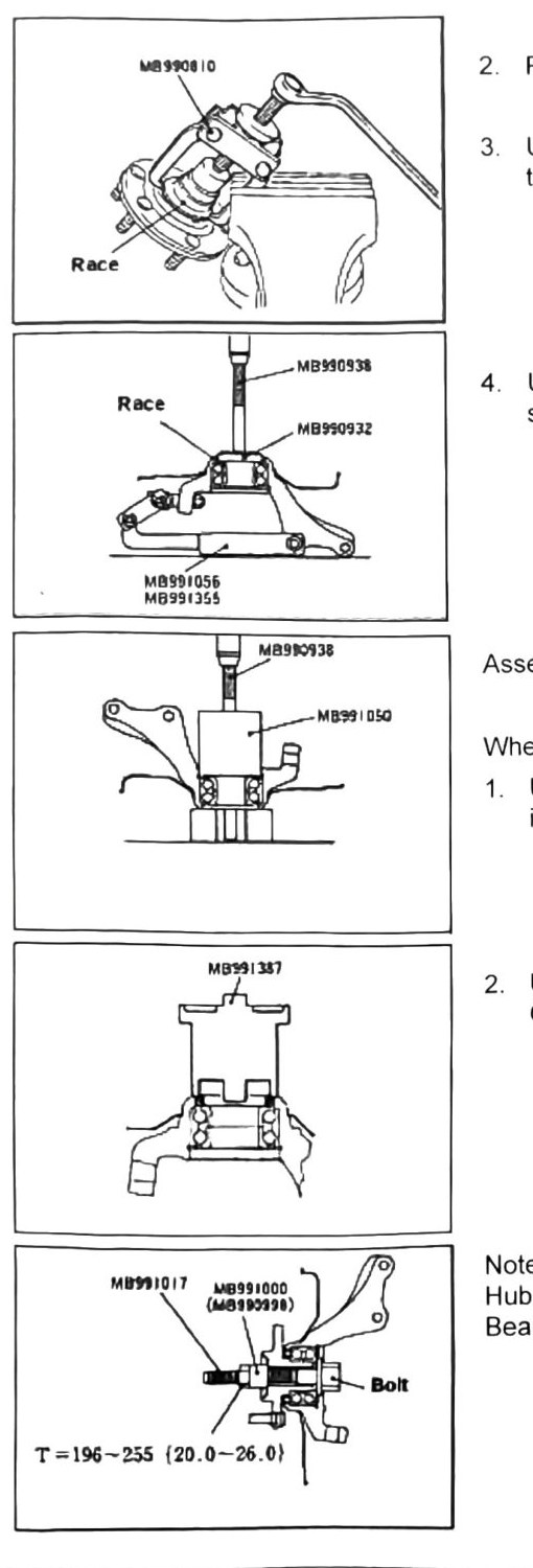
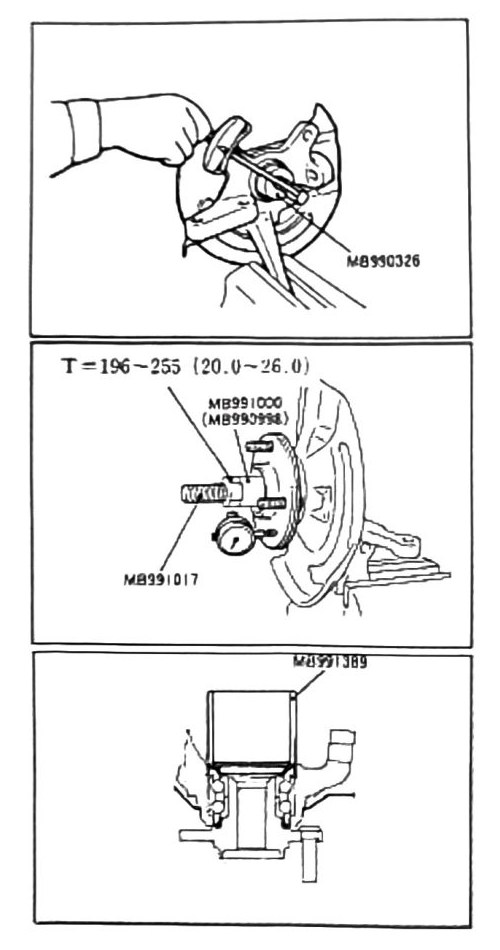
Assembly key points
Wheel bearing installation
- Use the tools shown (MB990938 drift with MB991050 wheel bearing adapter) to properly install a new race & bearing. (verified against scan p.205, 2026-08-30 — bearing removal on the same page uses MB990938 with MB990932, over knuckle supports MB991056/MB991355.)
- Use adapter MB991387 to install a new outer oil seal. (verified against scan p.205, 2026-08-30 — both the step text and the panel label read MB991387; “MB991337” was an OCR misread. The hub-torque panel on p.205 shows MB991017 and MB991000 (MB990998) with T=196–255.)
Note: when installing the hub, continue to turn the hub while setting torque, to properly seat the bearing.
- With the knuckle placed in a vise, complete hub torque settings.
Torque: 196–255 Nm (20.0–26.0 kgf·m; 145–188 ft-lb).
Hub run out test
- With the hub still in the vise, attach a dial gauge.
- Rotate assembly and verify settings.
Limit: printed as 0.005 mm on p.206 — (verified against scan p.206, 2026-08-30): the scan is clearly legible and the printed page really does say “Limit: 0.005mm” — this was not an OCR error. It still conflicts by a factor of 10 with the 0.05 mm hub run out limit printed on p.197 and p.201 (Run Out Testing); the manual itself is internally inconsistent here. The more permissive 0.05 mm appears twice elsewhere and is the likelier intended spec, but that judgment cannot be settled from the scans — treat 0.05 mm as the working limit and note the p.206 discrepancy.
- Install inner oil seal.
- Reassemble hub & knuckle assembly onto vehicle.