Front Axels & CV Joints Overhaul (4WD)
Note: see Hub & Knuckle Overhaul for hub & knuckle removal details — this section covers the drive axles and CV joints themselves.
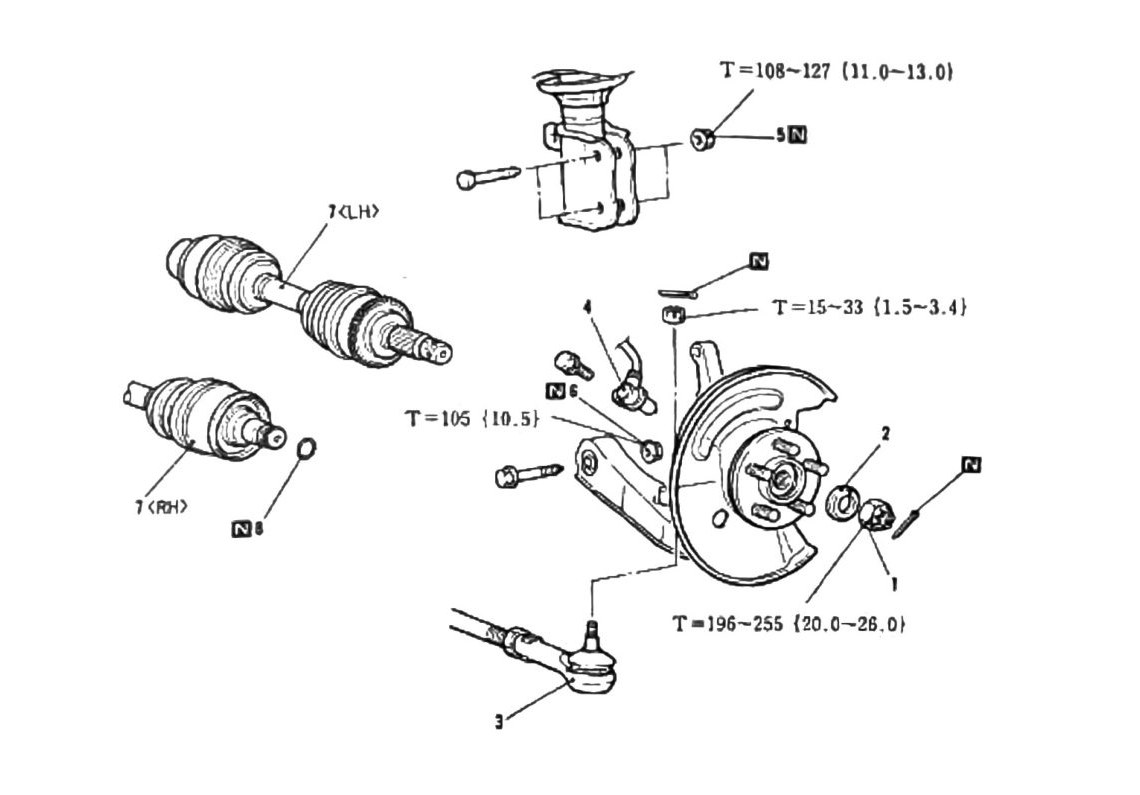
Component removal
- Castle Nut
- Washer
- Hub, Knuckle, and Tie Rod End
- Wheel Speed Sensor (ABS vehicles)
- Hub & Knuckle Assembly
- Lower Arm & Cross Member Attachment Bolts
- Drive Shaft Axels
- Circle Clip
Fastener torques
| Torque | Nm (kgf·m) |
|---|---|
| T = 108–127 | (11.0–13.0; 80–94 ft-lb) |
| T = 105 | (10.5; 77 ft-lb) |
| T = 15–33 | (1.5–3.4; 11–24 ft-lb) |
| Castle Nut Torque: T = 196–255 | (20.0–26.0; 145–188 ft-lb) |
Note: see following pages for removal and installation key points.
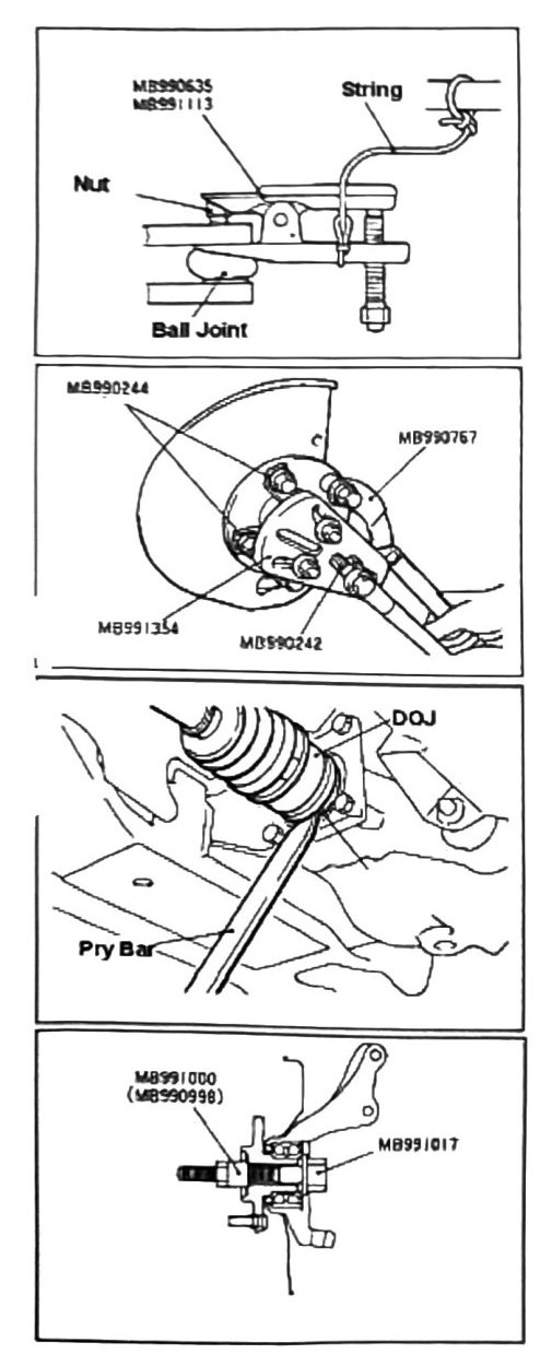
Tie rod removal
Tools: MB990635 (Linkage Press), plus a second tool printed as “MB:99:113” (verify printed p.208 — same illegible tool number as the Hub & Knuckle section).
- Attach a piece of string as shown to prevent the tie rod press from dropping after removing the tie rod.
- Press out tie rod. Ball joint tools: MB990244 (or “MB9990244” as printed), MB990767 (Hub Placement Holder).
Drive axle removal
- Attach the tools listed in the diagram: MB991354 (Puller Plate), MB990242 (as printed; likely MB990241 Axel Shaft Puller — verify printed p.208).
- Press out drive axle.
- Once the axle has been pressed, use a pry bar to back out the unit.
Note: never use a hammer to knock out shafts — damage will occur.
- For on-vehicle bearing removal, use tools MB991000/MB990998 (Spacer) and MB991017 (Front Hub Reamer & Installer).
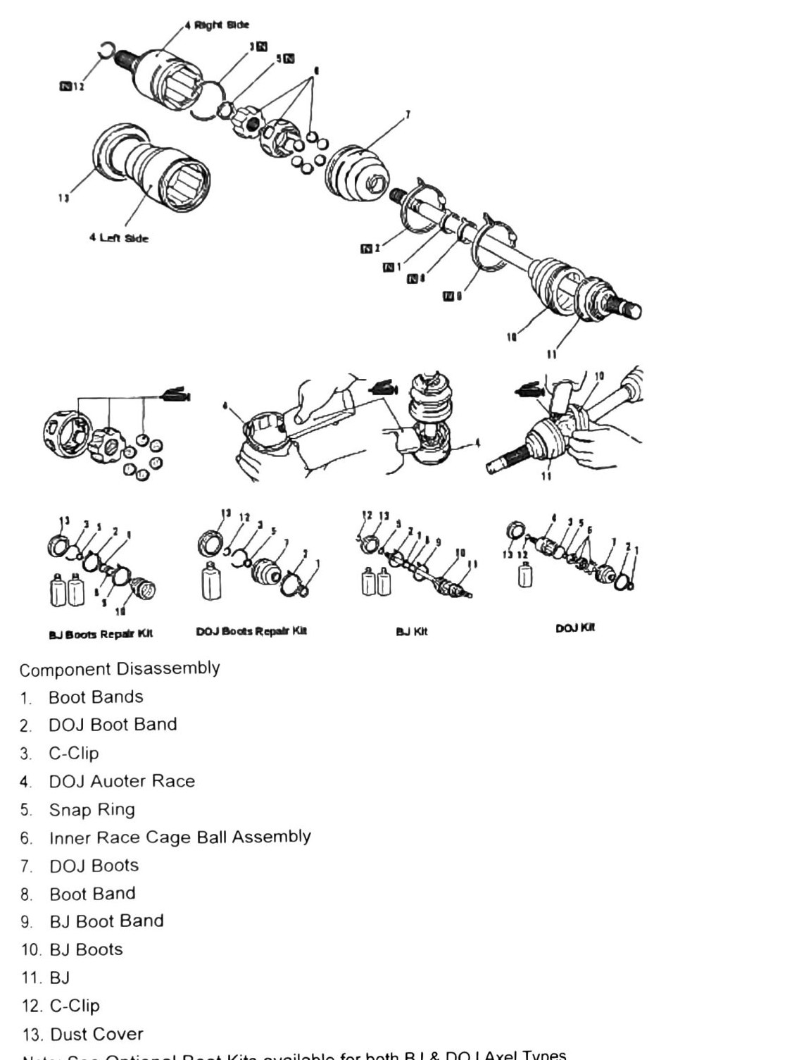
BJ/DOJ boot repair kits — component disassembly
Right-side and left-side BJ and DOJ boot repair kits are shown separately in the source diagram.
BJ kit:
- Boot Band (BJ)
- BJ Boots
- BJ (outer race/joint — label ambiguous, see flag below)
- C-Clip
- Dust Cover
DOJ kit:
- Boot Band (DOJ)
- DOJ Outer Race
- Snap Ring
- Inner Race Cage/Ball Assembly
- DOJ Boots
- Boot Band
(verify printed p.209) — the numbered component list (1-13 in the source) interleaves BJ and DOJ parts against a two-panel diagram; several stray OCR tokens (“N12”, “N1”, “2006”) could not be resolved to labels and are omitted. Item 11 (“BJ”) is ambiguous — likely “BJ Outer Race” or “BJ Joint” by analogy with the DOJ side, but not confirmed.
Note: optional boot kits are available for both BJ & DOJ axle types.
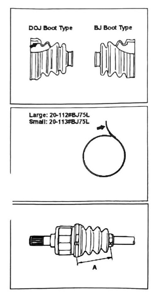
Boot type & length inspection
| Boot | Size code (as printed) |
|---|---|
| DOJ / BJ — Large | 20-112#BJ75L |
| DOJ / BJ — Small | 20-113#BJ75L |
(verify printed p.210) — the boot type/size table and the phrase printed as “Boot Type Differential ties” did not resolve cleanly; the two size codes above could not be confidently attributed to BJ vs. DOJ specifically. Do not order boot kits by these codes without confirming against a clean copy or the parts catalogue.
Note: boots must be tight to prevent air from entering the internal area and ballooning. Ballooning can cause early boot failure.
DOJ boot length inspection
DOJ boot length must be 80 ± 3 mm (3.150 ± 0.118 in), or failure may occur.