Emission Control Schematics — SOHC & DOHC
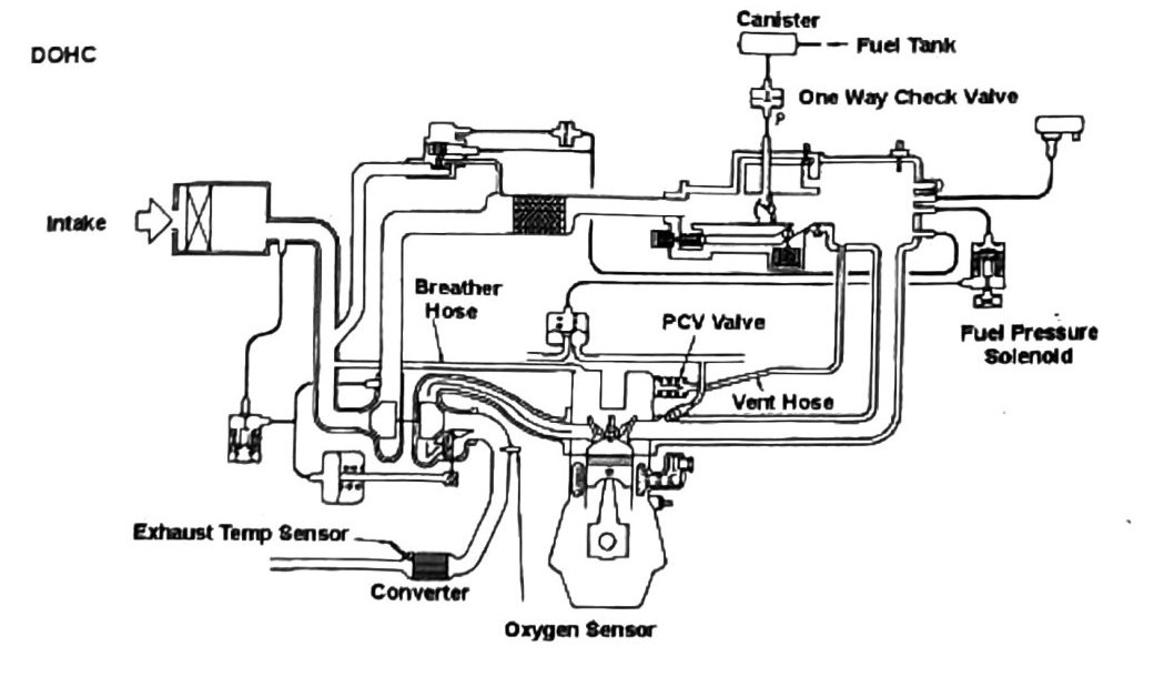
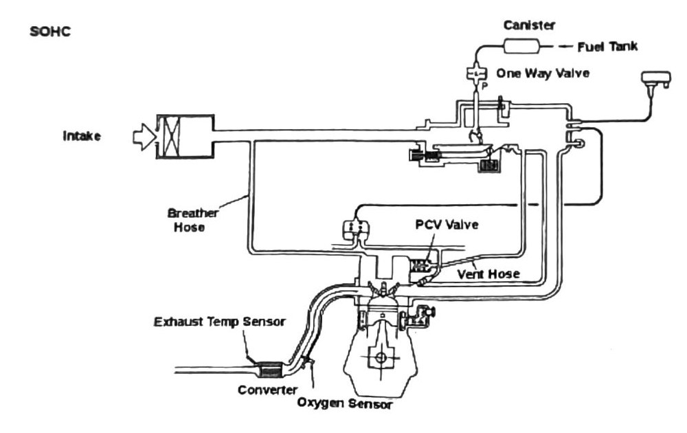
Emission control system diagrams (printed p.140)
Two schematics are shown, DOHC and SOHC, both circle the same core components:
- Canister
- Fuel Tank
- Intake Breather Hose
- One-Way (Check) Valve
- PCV Valve
- Exhaust Temp Sensor
- Vent Hose
- (Catalytic) Converter
- Oxygen Sensor
(verify printed p.140) — the SOHC diagram’s component list includes a “Fuel Pressure Solenoid,” which elsewhere in this chapter (see MPI Fuel System Sensor & Component Location Guide) is listed as “Fuel Pressure Control Valve DOHC” — i.e. a DOHC-only part. This may be an OCR mix-up between the two adjacent schematics rather than a genuine SOHC component; do not assume SOHC vehicles have this solenoid without checking a clean scan.
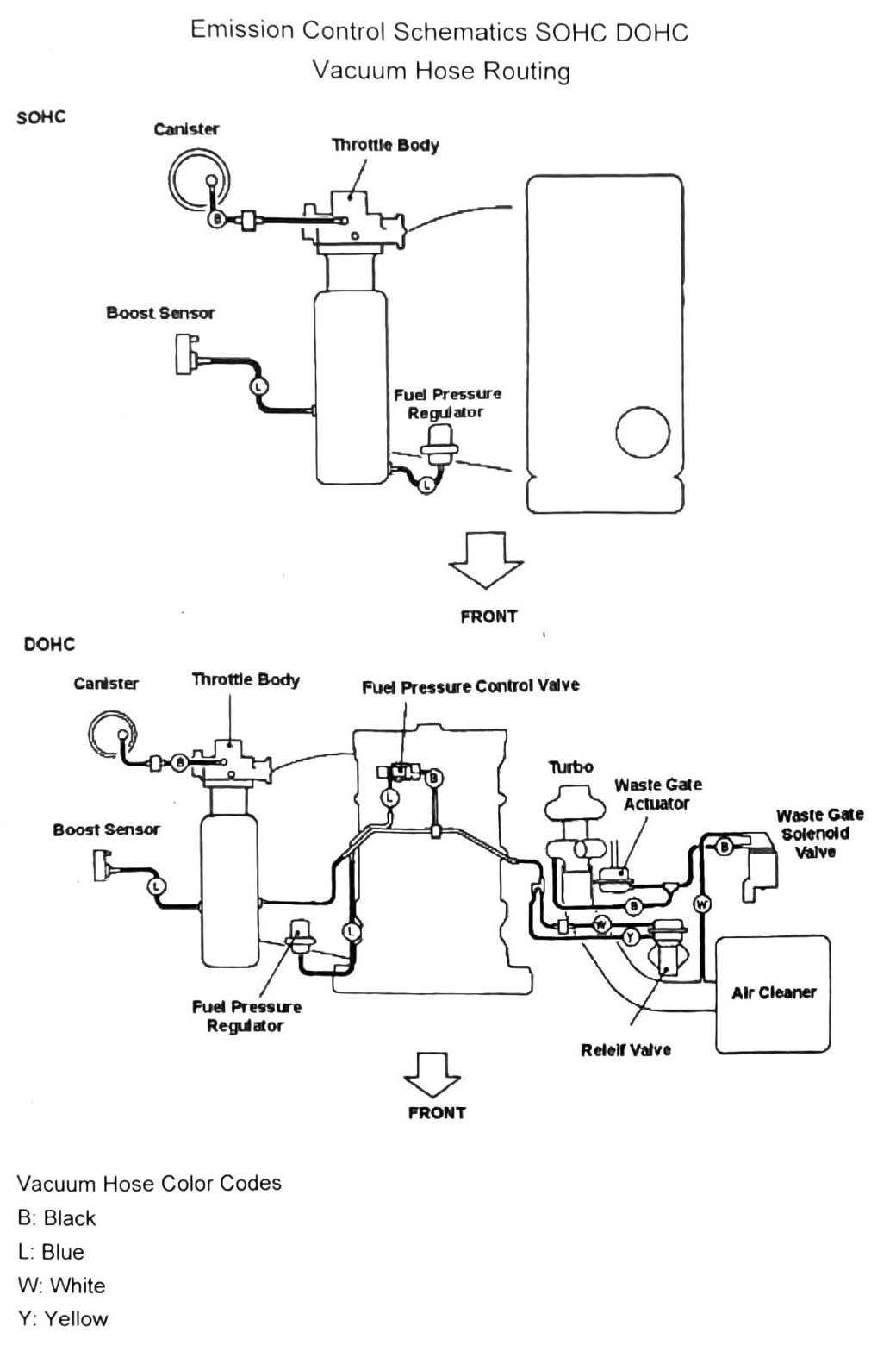
Vacuum hose routing (printed p.141)
SOHC:
- Canister, Throttle Body, Fuel Pressure Regulator
- “Boost Sensor” also appears in this diagram’s SOHC component list — (verify printed p.141): SOHC is naturally aspirated and should have no boost sensor; likely bleed-through from the adjacent DOHC diagram, same caution as noted in MPI Fuel System & Component Chart — SOHC.
DOHC (Turbo):
- Canister, Throttle Body, Fuel Pressure Control Valve, Boost Sensor, Fuel Pressure Regulator
- Turbo, Waste Gate Actuator, Relief Valve, Waste Gate Solenoid Valve, Air Cleaner
Vacuum hose color codes
| Code | Color |
|---|---|
| B | (not recoverable — likely Black) |
| L | (not recoverable — likely Blue) |
| Y | Yellow |
| W | (not recoverable — likely White) |
(verify printed p.141) — only the “Y: Yellow” pairing survived OCR intact; the color names for codes B, L, and W are inferred from context (a “Black / Blue / White” word list appears elsewhere on the same page but not adjacent to its matching letter code) and are not confirmed. Do not use these hose-color codes for routing verification without checking a clean scan.