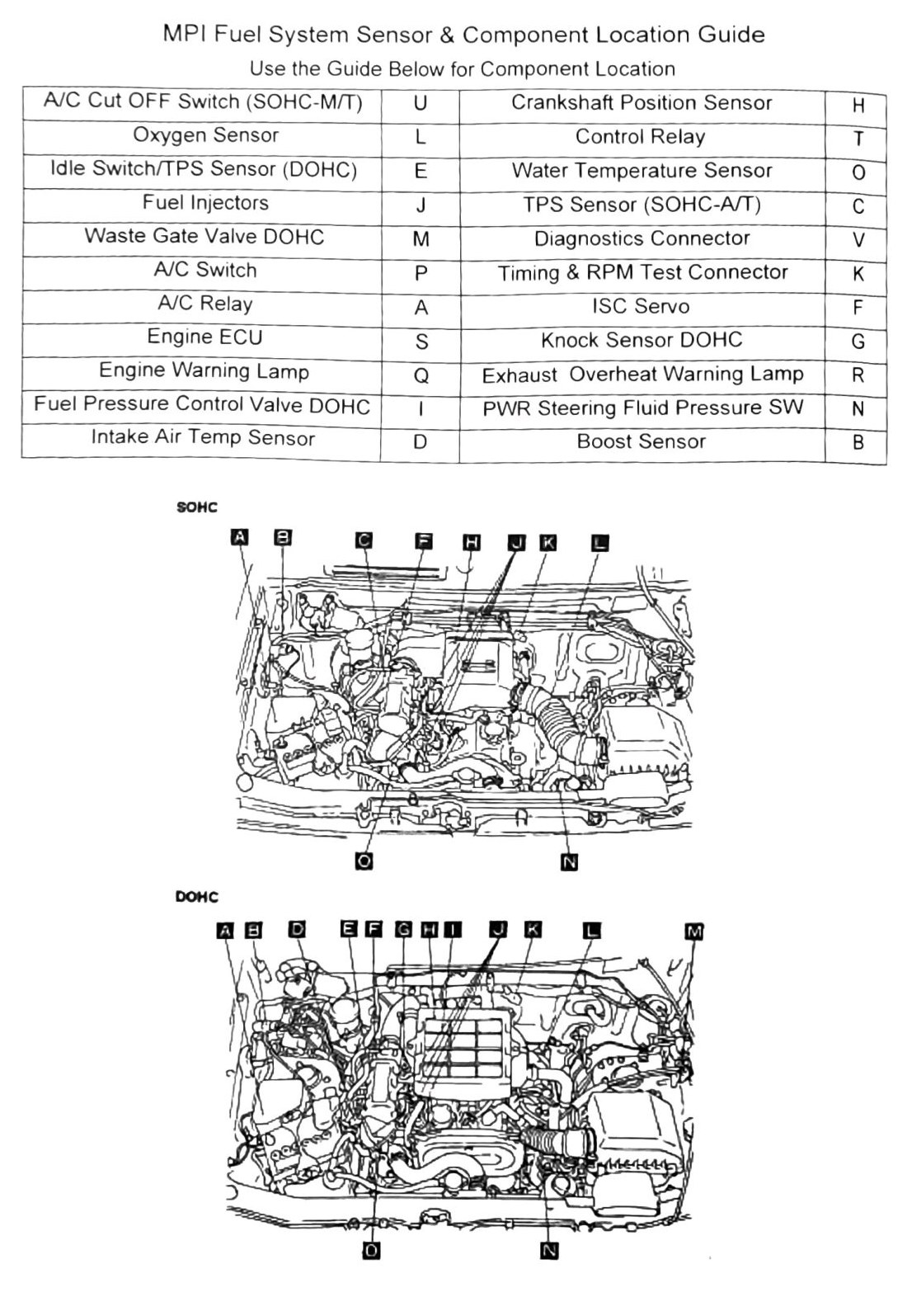
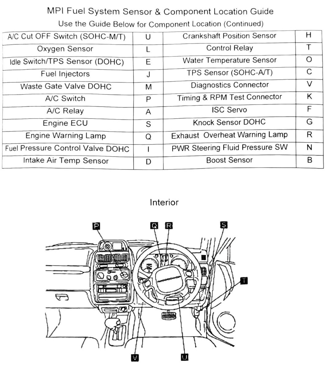
MPI Fuel System Sensor & Component Location Guide
A two-page visual legend mapping each sensor/component name to a lettered callout on an underhood location diagram (SOHC and DOHC layouts shown separately). The diagram itself, and almost all of its letter-to-component pairings, did not survive OCR — the scan returned the component name list and a scattered set of single letters, but not which letter belongs to which name for most entries.
Components shown on this page (both SOHC and DOHC guides)
- A/C Cut OFF Switch (SOHC-M/T)
- Oxygen Sensor
- Crankshaft Position Sensor
- Control Relay
- Idle Switch / TPS Sensor (DOHC)
- Water Temperature Sensor
- Fuel Injectors
- TPS Sensor (SOHC-A/T)
- Waste Gate Valve (DOHC)
- Diagnostics Connector
- A/C Switch
- Timing & RPM Test Connector
- A/C Relay
- ISC Servo
- Engine ECU
- Knock Sensor (DOHC)
- Engine Warning Lamp
- Exhaust Overheat Warning Lamp
- Fuel Pressure Control Valve (DOHC)
- Power Steering Fluid Pressure Switch
- Intake Air Temp Sensor
- Boost Sensor
Confirmed letter callout
- Intake Air Temp Sensor = “D” — this is the only component/letter pairing that appears identically positioned on both the printed p.132 and p.133 diagrams, giving reasonable confidence.
(verify printed p.132-133) — every other letter (A, C, E, F, G, H, J, K, L, M, O, P, Q, S, T, U, V and the “CRNB” / “TOCVKFCRNB” strings) appears in the OCR text but could not be reliably matched to a specific component name above. Do not use any letter besides “D” (Intake Air Temp Sensor) as a confirmed location callout without checking a clean scan.