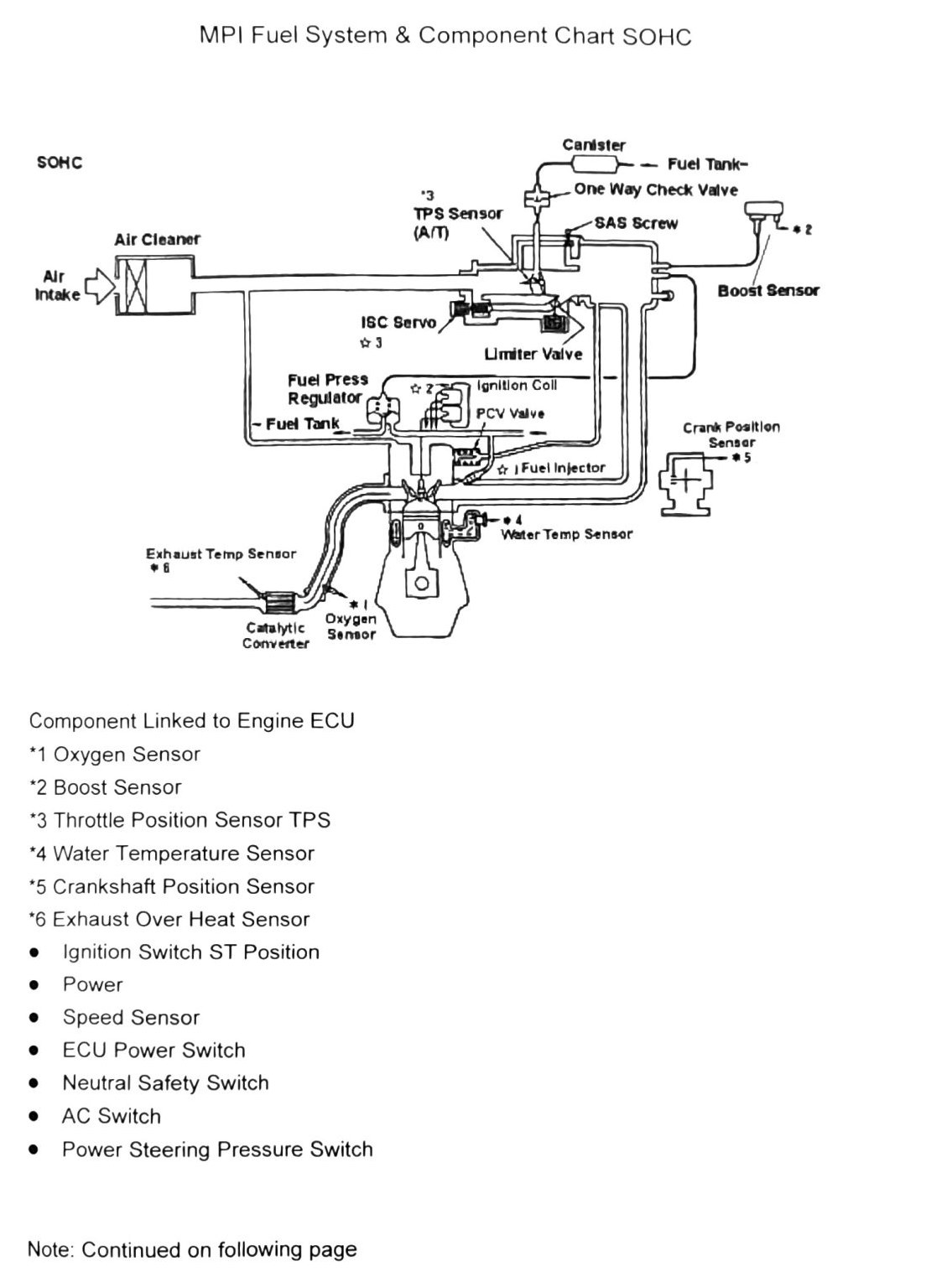
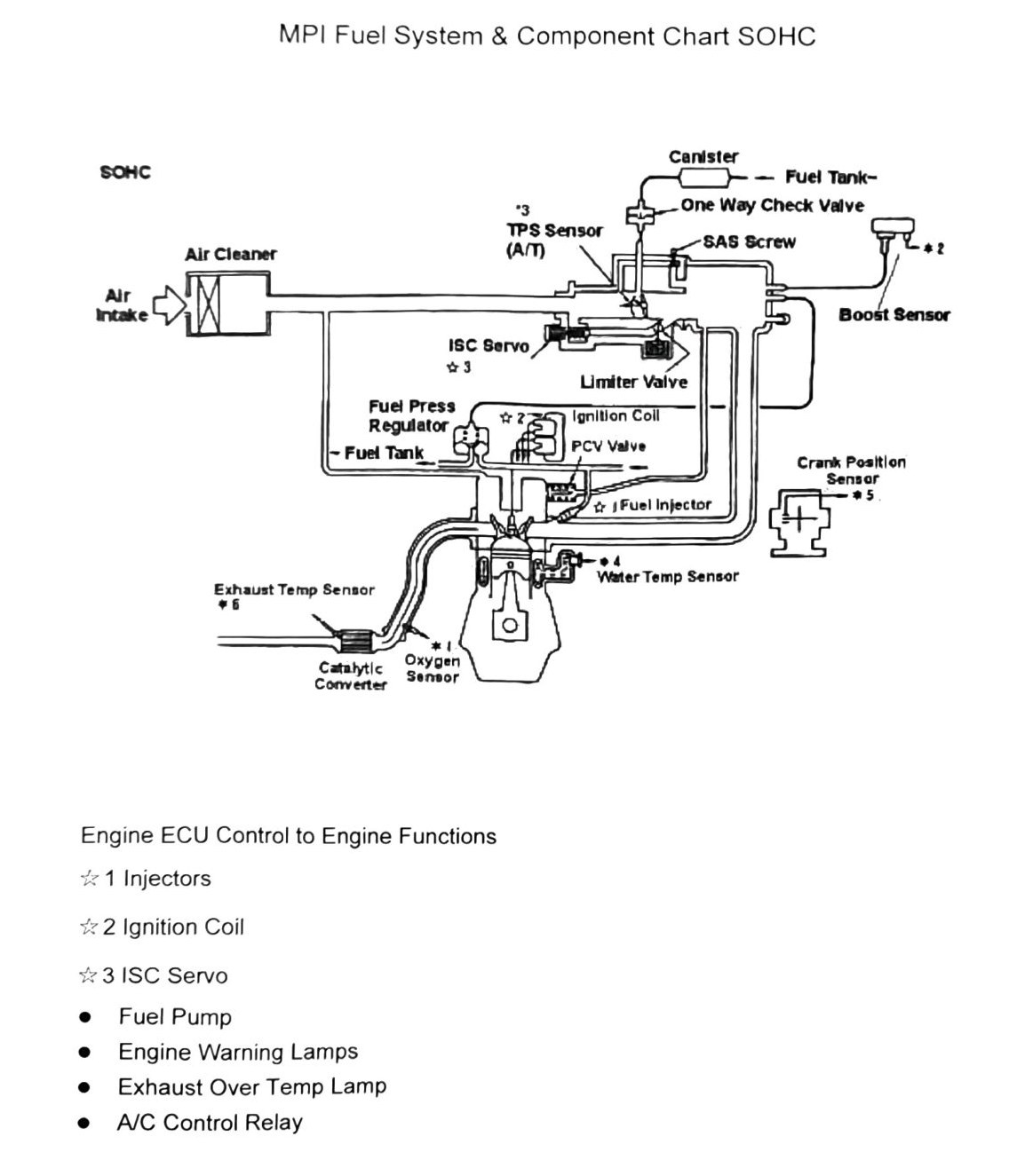
MPI Fuel System & Component Chart — SOHC
Component/system schematic for the naturally-aspirated SOHC MPI fuel system (XR grade). Two source diagrams cover the M/T and A/T variants; both share the same sensor/ECU loop, fuel tank, canister, and air-intake plumbing. OCR could not recover the diagram’s line-routing — only the labeled components below are transcribed with confidence.
Components linked to Engine ECU (inputs)
- Oxygen Sensor (*1)
- Boost Sensor (*2) — (verify printed p.117): SOHC is naturally aspirated (no turbo/boost), but “Boost Sensor” appears in this chart’s footnote list. Likely a shared chart template with the DOHC turbo chart; flag before publishing as SOHC-specific.
- Throttle Position Sensor, TPS (*3)
- Water Temperature Sensor (*4)
- Crankshaft Position Sensor (*5)
- Exhaust Over Heat Sensor (*6)
- Ignition Switch ST position
- ECU Power Switch
- Neutral Safety Switch
- A/C Switch
- Power Steering Pressure Switch
- Speed Sensor
Other diagram components (fuel/vacuum circuit)
- Fuel Tank, One-Way Check Valve, Canister, Air Cleaner
- SAS Screw (Speed Adjustment Screw), ISC Servo, Air Intake
- Fuel Pressure Regulator, Fuel Tank Limiter Valve
- Ignition Coil, PCV Valve
- Fuel Injector, Catalytic Converter
(verify printed p.117) — the TPS Sensor callout on this page reads “(AM)” in the OCR; by parallel with the p.118 chart’s “(A/T)” callout this is likely a garbled “(M/T),” but that is not certain.
ECU control outputs (printed p.118 chart, A/T variant)
- Injectors
- Ignition Coil
- ISC Servo
Additional outputs (unordered in source): Fuel Pump, Engine Warning Lamps, A/C Control Relay, Exhaust Over Temp Lamp.
(verify printed p.118) — the numbered callout order for the ECU-output list did not survive OCR cleanly (numbers 1-5 appear out of sequence against the bullet items); the component names above are legible, but which numbered diagram marker points to which component is not confirmed.