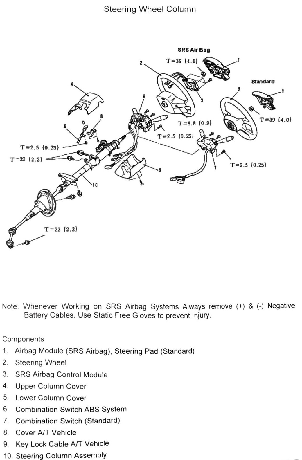
Steering Wheel Column
⚠️ SRS Airbag warning (as printed): whenever working on SRS airbag systems, always remove the (+) and (−) negative battery cables. Use static-free gloves to prevent injury/accidental deployment.
Components (printed p.289)
| # | Component |
|---|---|
| 1 | Airbag Module (SRS Airbag), Steering Pad (Standard) |
| 2 | Steering Wheel |
| 3 | SRS Airbag Control Module |
| 4 | Upper Column Cover |
| 5 | Lower Column Cover |
| 6 | Combination Switch (ABS-equipped vehicle) |
| 7 | Combination Switch (Standard) |
| 8 | Cover (A/T vehicle) |
| 9 | Key Lock Cable (A/T vehicle) |
| 10 | Steering Column Assembly |
Note: items 8-9 (Cover, Key Lock Cable) are called out specifically as A/T-vehicle parts — applicable to our truck (3A/T, 4WD).
Torque specifications
| Fastener | Torque |
|---|---|
| Fastener (unlabeled, ×1) | 39 N·m (4.0 kgf·m; 29 ft-lb) |
| Fastener (unlabeled, ×1) | 22 N·m (2.2 kgf·m; 16 ft-lb) |
| Fastener (unlabeled, ×1) | 8.8 N·m (0.9 kgf·m; 78 in-lb) |
| Fastener (unlabeled, ×1) | 2.5 N·m (0.25 kgf·m; 22 in-lb) |
OCR note: four distinct torque values appear on the printed diagram (some repeated at multiple callout points) but the fastener each one applies to is not legible from the scan. (verify printed p.289) before using these for reassembly torque.
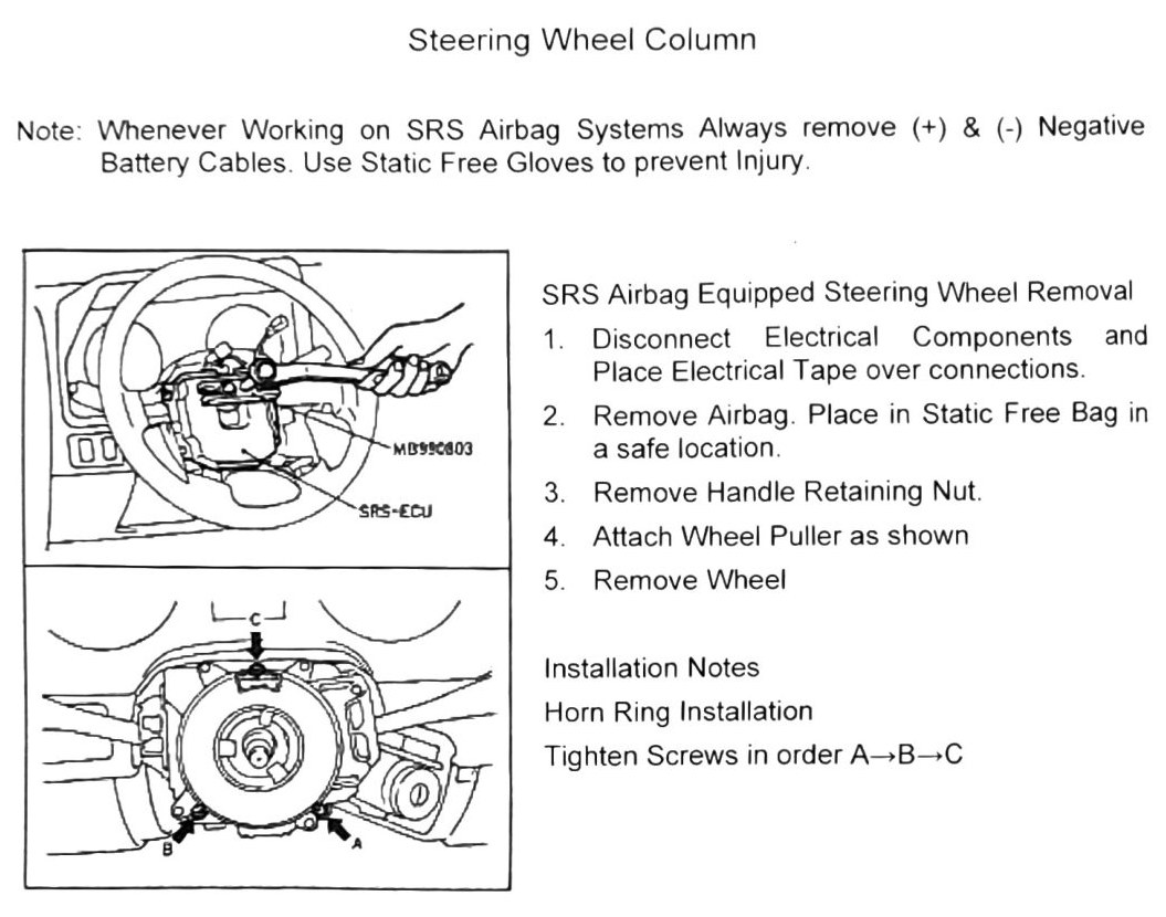
SRS airbag-equipped steering wheel removal (printed p.290)
- Disconnect the electrical connector at the SRS-ECU (tool MB990603). Place electrical tape over the disconnected connections.
- Remove airbag module; place it in a static-free bag in a safe location.
- Remove the handle retaining nut.
- Attach a wheel puller as shown.
- Remove the steering wheel.
Installation note — horn ring installation: tighten the horn ring screws in order A → B → C.
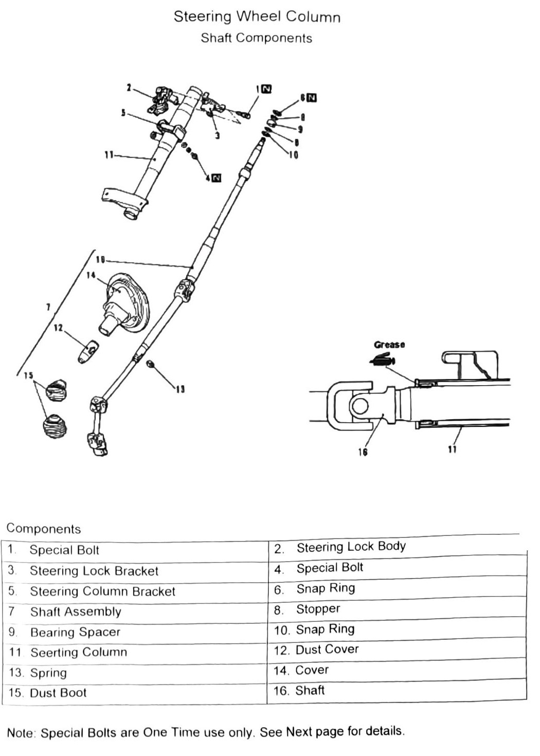
Shaft components (printed p.291)
| # | Component |
|---|---|
| 1 | Special Bolt |
| 2 | Steering Lock Body |
| 3 | Steering Lock Bracket |
| 4 | Special Bolt |
| 5 | Steering Column Bracket |
| 6 | Snap Ring |
| 7 | Shaft Assembly |
| 8 | Stopper |
| 9 | Bearing Spacer |
| 10 | Snap Ring |
| 11 | Steering Column |
| 12 | Dust Cover |
| 13 | Spring |
| 14 | Cover |
| 15 | Dust Boot |
| 16 | Shaft |
Note (as printed): special bolts (items 1 and 4) are one-time use only — see Key Lock Cylinder Lock Replacement for removal technique and replacement notes.