Front Strut Assembly
Note: anytime the front strut has been removed or adjusted, alignment inspection is required (see Data & Tools).
Component removal (vehicle)
Torque specifications
| Fastener | Torque |
|---|---|
| Brake hose bracket retaining bolt | 19 N·m (1.9 kgf·m; 168 in-lb) |
| Strut lower attachment bolts | 108-127 N·m (11.0-13.0 kgf·m; 80-94 ft-lb) |
Procedure
- Remove brake hose bracket retaining bolt.
- Remove brake hose bracket.
- Remove strut lower attachment bolts.
- Remove strut upper attachment nuts.
- Remove strut assembly.
- Installation is the reverse of removal.
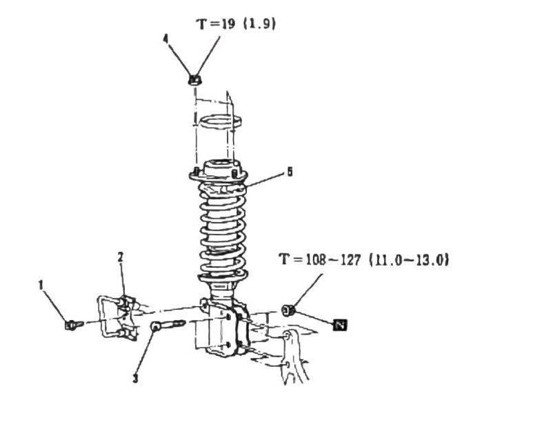
OCR note: the two torque values on this page are legible, but exact assignment (bracket bolt vs. lower attachment bolts) is inferred from typical fastener size/order rather than an explicit label pairing — (verify printed p.257).
Strut disassembly (bench)
Torque specification
| Fastener | Torque |
|---|---|
| Self Locking Nut | 49 N·m (5.0 kgf·m; 36 ft-lb) |
Components
| # | Component |
|---|---|
| 1 | Dust Cover |
| 2 | Self Locking Nut |
| 3 | Stopper |
| 4 | Cover Bracket |
| 5 | Insulator Rubber Grommet |
| 6 | Support Bracket |
| 7 | Bearing |
| 8 | Spring Upper Seat |
| 9 | Pump Rubber |
| 10 | Coil Spring |
| 11 | Strut |
Special tools
- Spring Compressor MB991239
- Strut Socket MB991109
- Allen Wrench (six-point) + small pipe (for turning wrench while loosening/tightening)
Procedure
- Place the strut in a vise.
- Use a spring compressor to take the pressure off the upper components.
- Use a six-point Allen wrench, as shown, in combination with a small pipe to turn the wrench while loosening or tightening.
- Replace components as necessary.
- Reassemble in reverse.
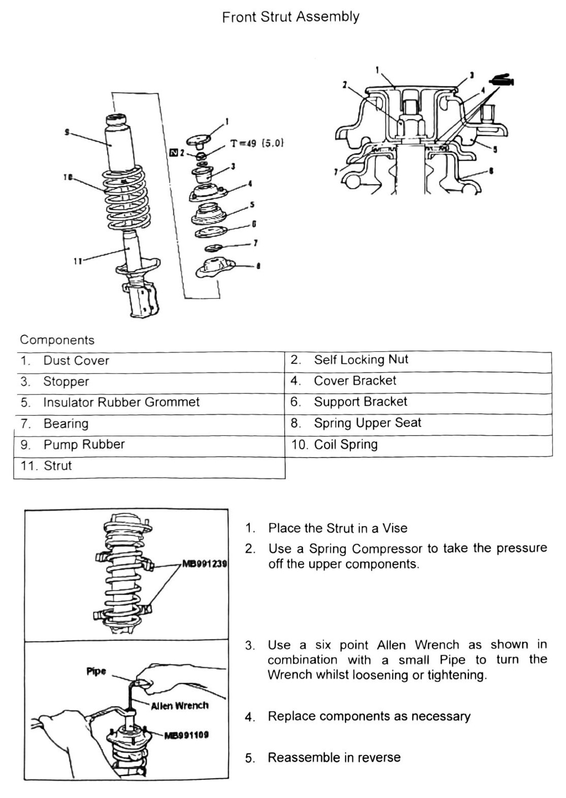
OCR note: the 11-item components list was split across two scrambled OCR columns; order above reconstructed from the printed item numbers (1–11), which were fully legible. The special-tool labels (“Pipe”, “Allen Wrench”, “Cover Bracket”) appeared interleaved with the MB991239/MB991109 part numbers in the raw scan, so the exact tool-to-part-number pairing shown above is inferred by cross-referencing the matching part numbers in Data & Tools rather than a direct in-page label — (verify printed p.258). Which specific fastener the 49 N·m self-locking-nut torque applies to (vs. any other fastener on this diagram) is likewise inferred, not directly labeled — (verify printed p.258).