Data & Tools
Front-end alignment specifications, special tools, and the toe-in/camber/caster adjustment procedure. Confirmed consistent across both source pages (the toe-in/camber/caster values repeat on printed p.256).
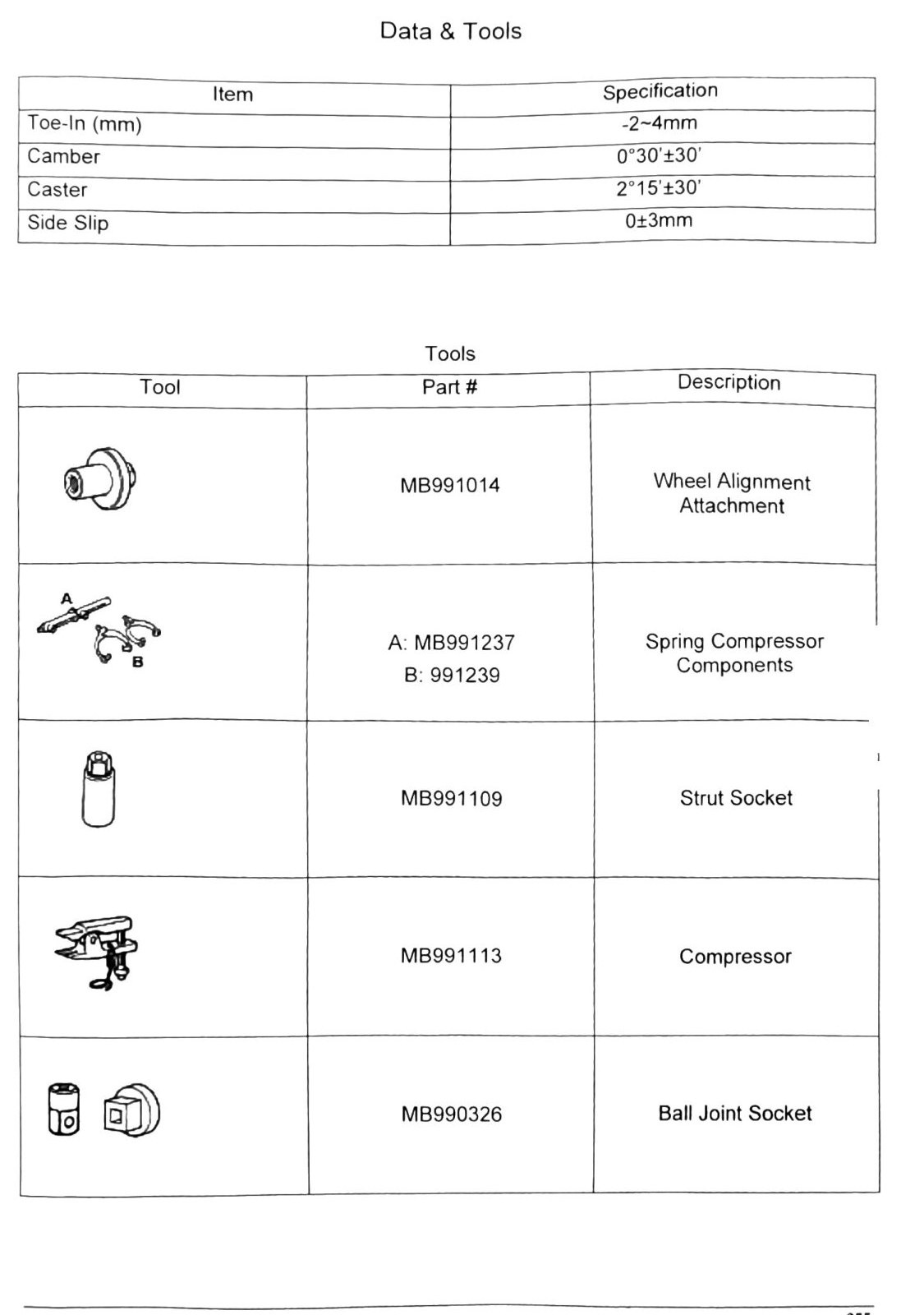
Alignment specifications
| Item | Specification |
|---|---|
| Toe-In | -2 ~ 4 mm (-0.079 ~ 0.157 in) |
| Camber | 0°30′ ± 30′ |
| Caster | 2°15′ ± 30′ |
| Side Slip | 0 ± 3 mm (0 ± 0.118 in) |
Special tools — Alignment / Spring Compressor set
| Tool | Part # | Description |
|---|---|---|
| Wheel Alignment Attachment | MB991014 | |
| Spring Compressor (Set) | A: MB991237 / B: MB991239 | |
| — Strut Socket (compressor component) | MB991109 | |
| — Compressor (compressor component) | MB991113 | |
| — Ball Joint Socket (compressor component) | MB990326 |
OCR note: the tool/part-number/description columns on this table were scrambled by the scan (Tool, Part #, and Description each printed as separate stacked lists rather than aligned rows). The part numbers themselves are legible, and the “Components” sub-heading in the source ties MB991109/MB991113/MB990326 to the Spring Compressor set — but the exact tool-name-to-part-number pairing for the top two rows is a reconstruction, not a direct read. (verify printed p.255) before ordering tooling off this table alone.
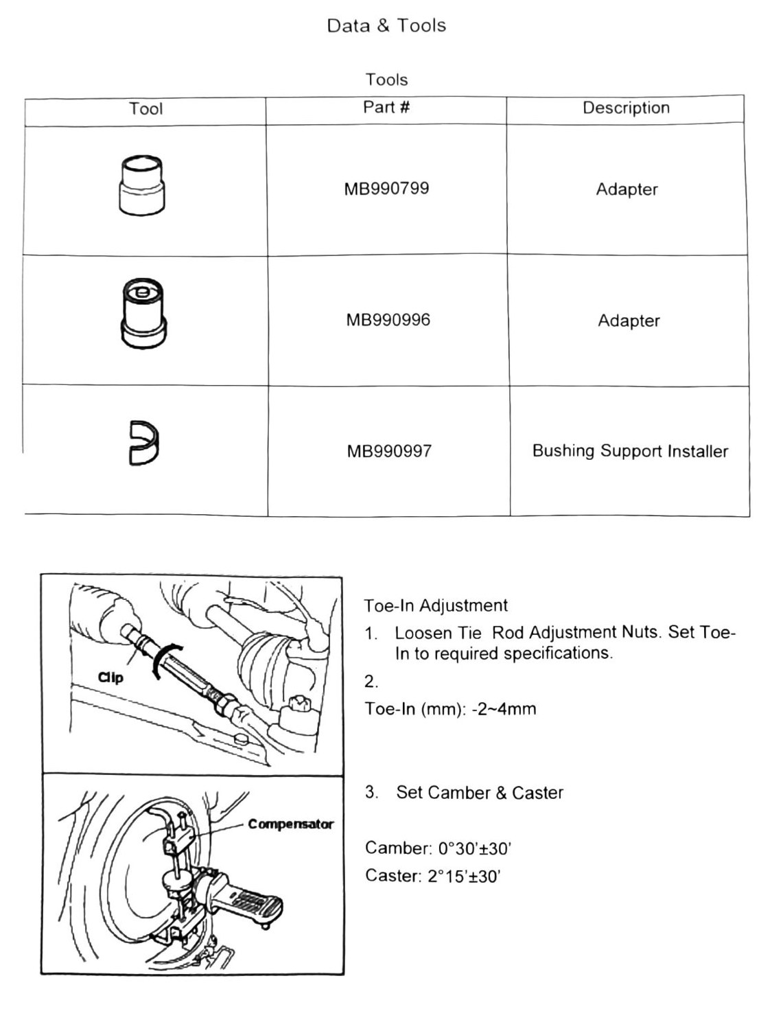
Special tools — Bushing / Toe-In Adjustment
| Tool | Part # | Description |
|---|---|---|
| ? | MB990799 | Adapter |
| ? | MB990996 | Adapter |
| ? | MB990997 | Bushing Support Installer |
OCR note: three additional tool-name candidates appeared on this page with no part number attached — “Toe-In Adjustment”, “Clip”, “Compensator” — and could not be confidently paired to MB990799 / MB990996 / MB990997 above. (verify printed p.256) for the correct tool name against each part number before ordering.
Toe-in adjustment procedure
- Loosen tie rod adjustment nuts. Set toe-in to required specification.
- Toe-In: -2 ~ 4 mm (-0.079 ~ 0.157 in)
- Set camber & caster:
- Camber: 0°30′ ± 30′
- Caster: 2°15′ ± 30′