Driveshaft U-Joint Replacement
Component identification
- Flange Yoke
- Sleeve Yoke
- Driveshaft
Note: U-joints must be replaced as a set. Individual components cannot be replaced individually.
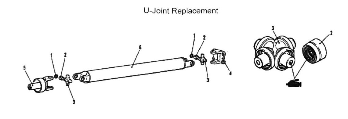
U-joint removal procedure
Required tool: C-clamp MB990840 (or equivalent) is required for this procedure.
- Remove snap rings.
- Remove bearing caps and inspect. Replace if damaged.
- Place the C-clamp as shown.
- Press out the U-joint; remove cups from both ends.
- Slide out U-joint.
- Inspect U-joint for cracking or fractures. Replace if damaged.
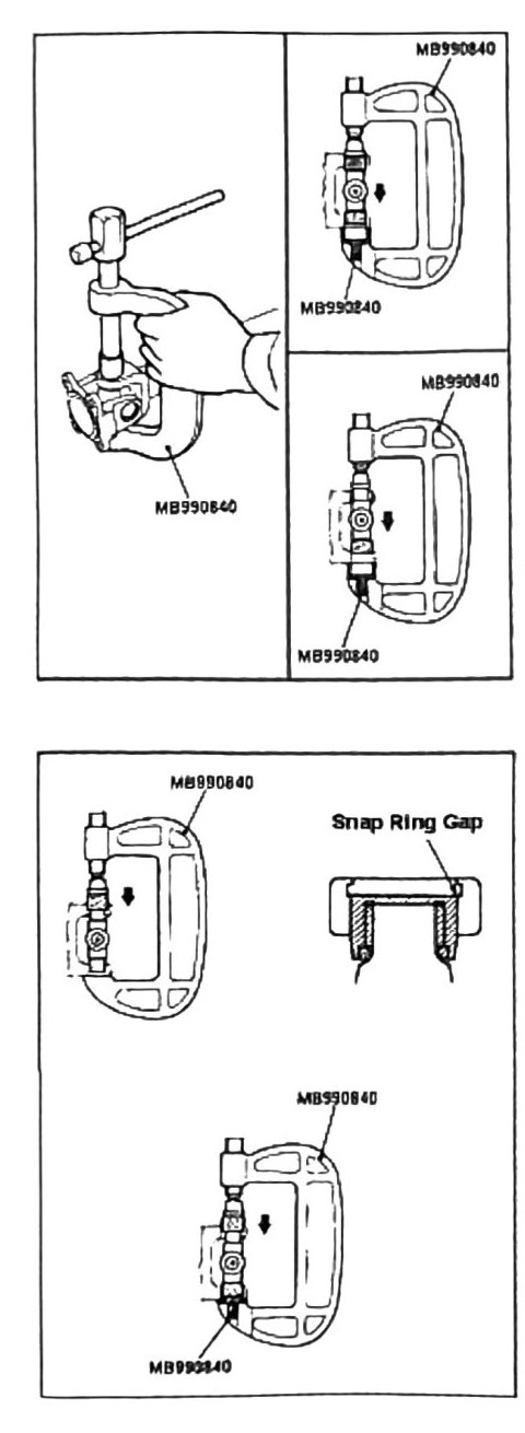
U-joint assembly
Note: Coat all parts to be pressed thoroughly with multi-grade axle grease before installation.
- Place U-joint in C-clamp press as shown.
- Compress cups as shown in the diagram.
Note: If cups cannot be compressed by hand-tightening, or binding has occurred, remove cups and inspect needle bearings.
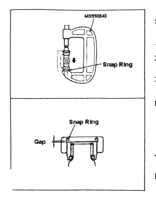
Snap ring installation
- Place the U-joint as shown.
- Coat snap ring with multi-grade axle grease.
- Install snap ring — use Needle Nose pliers or similar tools if C-clamp adapter tool MB990840 is not available.
- After installation, measure snap ring-to-bearing-cup gap.
Limit: 0.03 mm (0.001 in).
Snap ring thickness guide
| Snap Ring Thickness | Color Code (painted) |
|---|---|
| 1.28 mm (0.050 in) | ----- (no paint mark) |
| 1.31 mm (0.052 in) | Yellow |
| 1.34 mm (0.053 in) | Blue |
| 1.37 mm (0.054 in) | Purple |
(verified against scan p.196, 2026-08-30) — the printed chart pairs the three color names one row lower than the earlier transcription had them: 1.28 mm carries no color code (printed as ”-----”), and Yellow/Blue/Purple belong to 1.31/1.34/1.37 mm respectively.