A/T Positioning Inhibitor Switch
Applies directly to our truck.
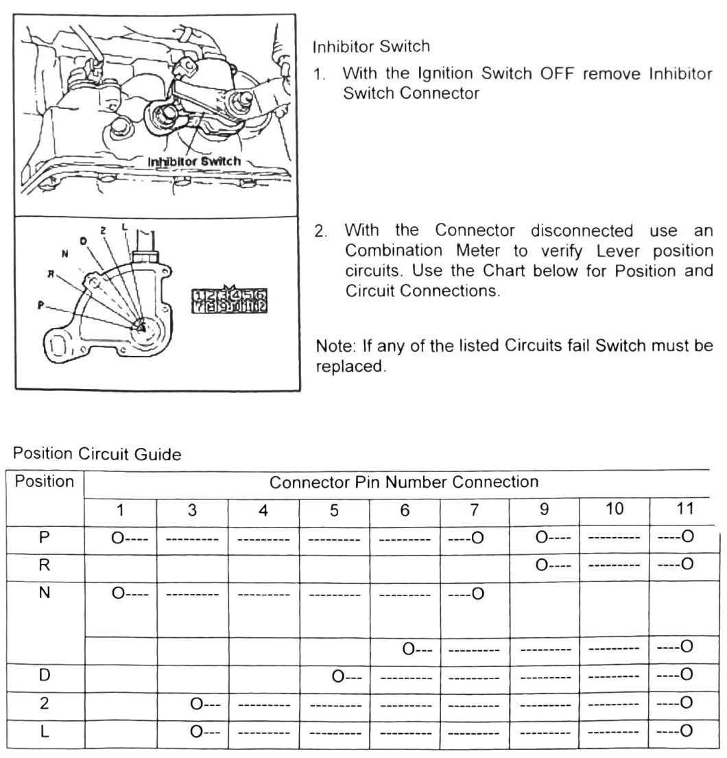
Inhibitor switch test
- With the ignition switch OFF, remove the Inhibitor Switch connector.
- With the connector disconnected, use a combination meter to verify lever-position circuits. Use the position/circuit chart to identify the expected pin connections for each lever position.
Note: If any of the listed circuits fail, the switch must be replaced.
(verify printed p.179) — the “Position Circuit Guide” table (lever positions P / R / N / D / 2 / L against connector pins 5, 6, 7, 9, 10, 11) did not survive OCR with a reliable position-to-pin mapping; the continuity symbols and pin numbers could not be confidently paired. Do not guess this mapping — check the printed table before performing this test.
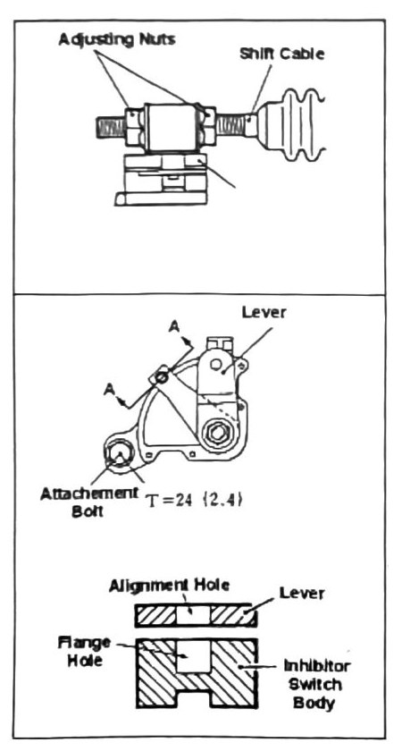
Inhibitor switch & shift cable adjustment
- Loosen adjustment nuts and draw cable to proper position.
- Tighten adjustment nuts.
Inhibitor switch adjustment
Note: Before adjusting the Inhibitor Switch, confirm shifter cable positioning. It is best practice not to loosen both the Inhibitor Switch and cable at the same time.
- If Inhibitor Switch position adjustment is required, loosen the attachment bolt.
- Preliminary adjustment should follow the lower-left positioning guide (per diagram).
- Tighten adjustment bolt.
Note: Do not over-tighten the adjustment bolt — the case may crack and the unit must be replaced.
| Torque callout | N·m (kgf·m) |
|---|---|
| T=24 (18 ft-lb) | (2.4) — Shift cable attachment bolt |