A/T ECU Computer Pin Guide
Applies directly to our truck.
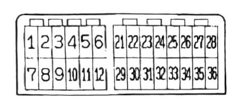
Pin table
| Pin # | Circuit | Condition | Reading |
|---|---|---|---|
| 1 | Shift Control Solenoid Valve No.1 | Lever POS “D” | 0V |
| 1 | Shift Control Solenoid Valve No.1 | Lever POS “2” | 12-14V |
| 6 | TPS Sensor | Full Closed (Idle) | 0.4-1.0V |
| 6 | TPS Sensor | Full Open (Throttle) | 4.5-5.5V |
| 7 | Battery Power | IGN Switch OFF | 0V |
| 7 | Battery Power | IGN Switch ON | 12-14V |
| 9 | Ground (-) | — | 0V |
| 10 | Ground (-) | — | 0V |
| 12 | Throttle Position Sensor (+) | IGN Switch ON | 4.5-5.5V |
| 23 | Ignition Coil (-) | Engine Idle | 4.0-10.0V |
| 23 | Ignition Coil (-) | 3000+ RPM | 0.3-3.0V |
| 27 | Inhibitor Switch (Gear Position “2”) | Lever POS “2” | 12-14V |
| 28 | Inhibitor Switch POS “D” | Lever POS “D” | 12-14V |
| 30 | Speed Sensor (-) | Above 10km/h (6.2 mph) | AC 0.2V+ |
| 31 | Speed Sensor (+) | Above 10km/h (6.2 mph) | AC 0.2V+ |
| 35 | Inhibitor Switch POS “L” | Lever POS “L” | 12-14V |
Note: Not all pins are used.
(verify printed p.177) — Pin 2 (Shift Control Solenoid Valve No.2, Lever POS “L”) and Pin 3 (Shift Control Solenoid Valve No.3, Turbocharged) are not included in the table above. The source text runs these two rows together with a jumbled block of conditions/values (“0V”, “Lever POS D”, “Below 20% Throttle Opening 1-2 Shift”, “12-14V”, “12V (2Sec)”, “Engine: Idle”) that cannot be confidently split between the two pins. Given Pin 3 is the turbocharged-only solenoid, this gap is directly relevant to our truck — do not guess these two rows; check the printed page before using Pin 2/Pin 3 for diagnosis.