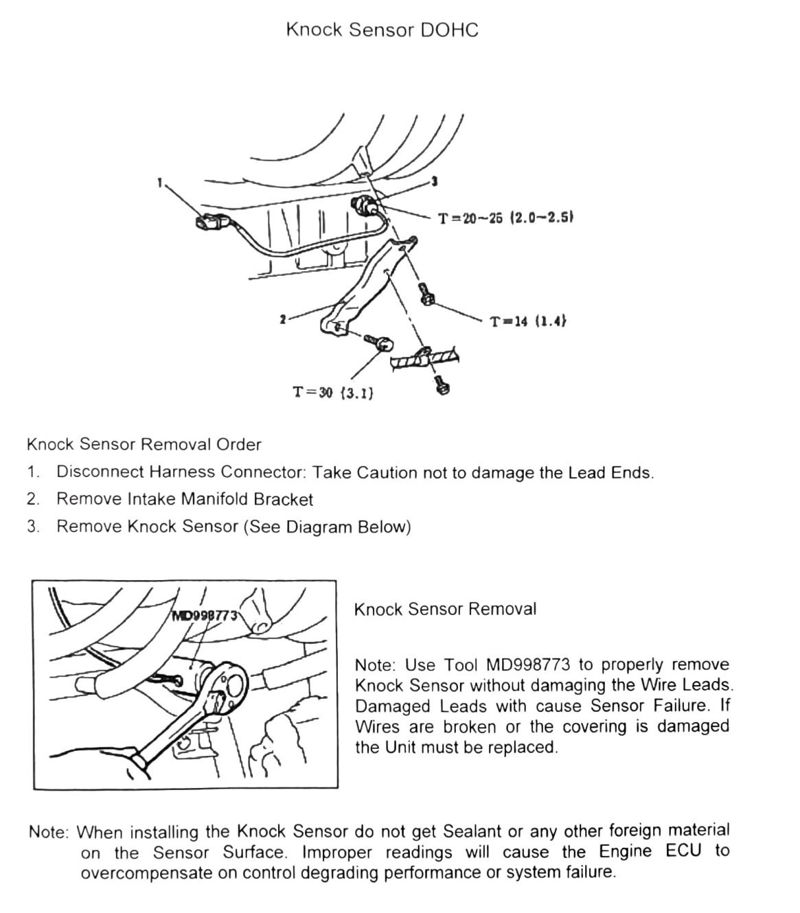
Knock Sensor (DOHC)
Unlike the other sections in this chapter, the source header for this page is “Knock Sensor DOHC” only — no SOHC variant is listed, consistent with the knock sensor being specific to the turbocharged DOHC engine. This applies directly and fully to our truck (4A30 DOHC turbo, VR-II).
Knock sensor removal order
- Disconnect the harness connector. Take caution not to damage the lead ends.
- Remove the intake manifold bracket.
- Remove the knock sensor (see diagram).
Special tool
- MD998773 — use this tool to remove the knock sensor without damaging the wire leads.
Note: damaged leads will cause sensor failure. If wires are broken or the covering is damaged, the unit must be replaced.
Note: when installing the knock sensor, do not get sealant or any other foreign material on the sensor surface. Improper readings will cause the engine ECU to overcompensate on control, degrading performance or causing system failure.
Torque specifications
| Torque callout | N·m (kgf·m) | Imperial |
|---|---|---|
| T=30 | (3.1) | 22 ft-lb |
| T=20-26 | (2.0-2.5) | 15-19 ft-lb |
| T=14 | (1.4) | 124 in-lb |
(verify printed p.163) — three torque callouts are legible on the diagram, but the leader lines tying them to specific fasteners did not survive OCR as text. Plausible candidates are the knock sensor’s own retaining bolt, the intake manifold bracket bolt(s), and a harness clamp/bracket fastener, but none of the three values could be confidently matched to a specific fastener — do not torque any of these components from this table alone without checking the printed diagram.