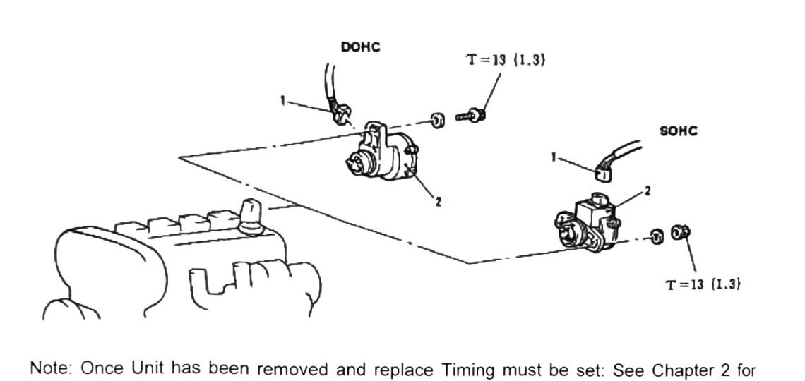
Crankshaft Position Sensor (Distributor) (DOHC & SOHC)
Header is “DOHC-SOHC” and both torque callouts on this page are identical, so this procedure applies to both engines without a spec split — including our truck’s DOHC turbo.
Note: once the unit has been removed and replaced, timing must be reset. See Chapter 2 for timing settings.
Note: if the original crankshaft position sensor will be reinstalled, mark the adjustment slide portion with indelible ink, and place a corresponding mark on the cylinder head directly above it, for easy reinstallation alignment.
Component removal
- Rotate the engine to TDC (verify TDC with cylinder #1).
- Disconnect the harness connector.
- Remove the retaining bolt (item 1) and slide the sensor out toward the firewall.
- Install in reverse order. See timing settings (Chapter 2).
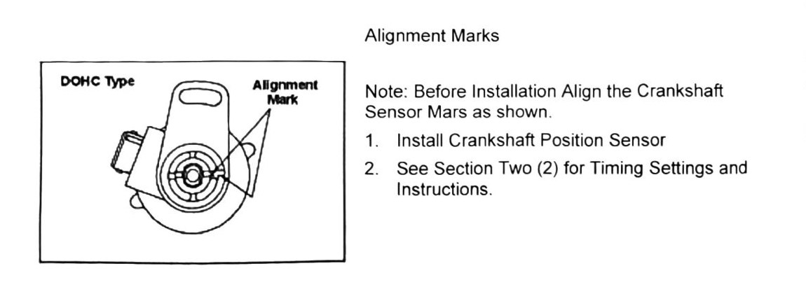
Alignment (DOHC type)
Note: before installation, align the crankshaft sensor marks as shown in the diagram.
- Install the crankshaft position sensor.
- See Chapter 2 (“Section Two”) for timing settings and instructions.
(verify printed p.162) — the alignment sub-section is explicitly headed “DOHC Type” in the source; no separate SOHC alignment-mark diagram or instructions appear on this page. Whether SOHC uses the same alignment marks/procedure or a page not captured in this chapter is not stated — do not assume the DOHC alignment procedure applies unmodified to a SOHC engine.
Torque specification
| Engine | Torque |
|---|---|
| DOHC | T = 13 N·m (1.3 kgf·m; 115 in-lb) |
| SOHC | T = 13 N·m (1.3 kgf·m; 115 in-lb) |
Both callouts are the same value on this page — no DOHC/SOHC torque split for the retaining bolt.