Alternator
Applies to both SOHC and DOHC engines — the source pages are headed “SOHC-DOHC” (OCR renders this as “SOHS-DOHC”) on all three pages, indicating no split between the two engine types for the alternator itself.
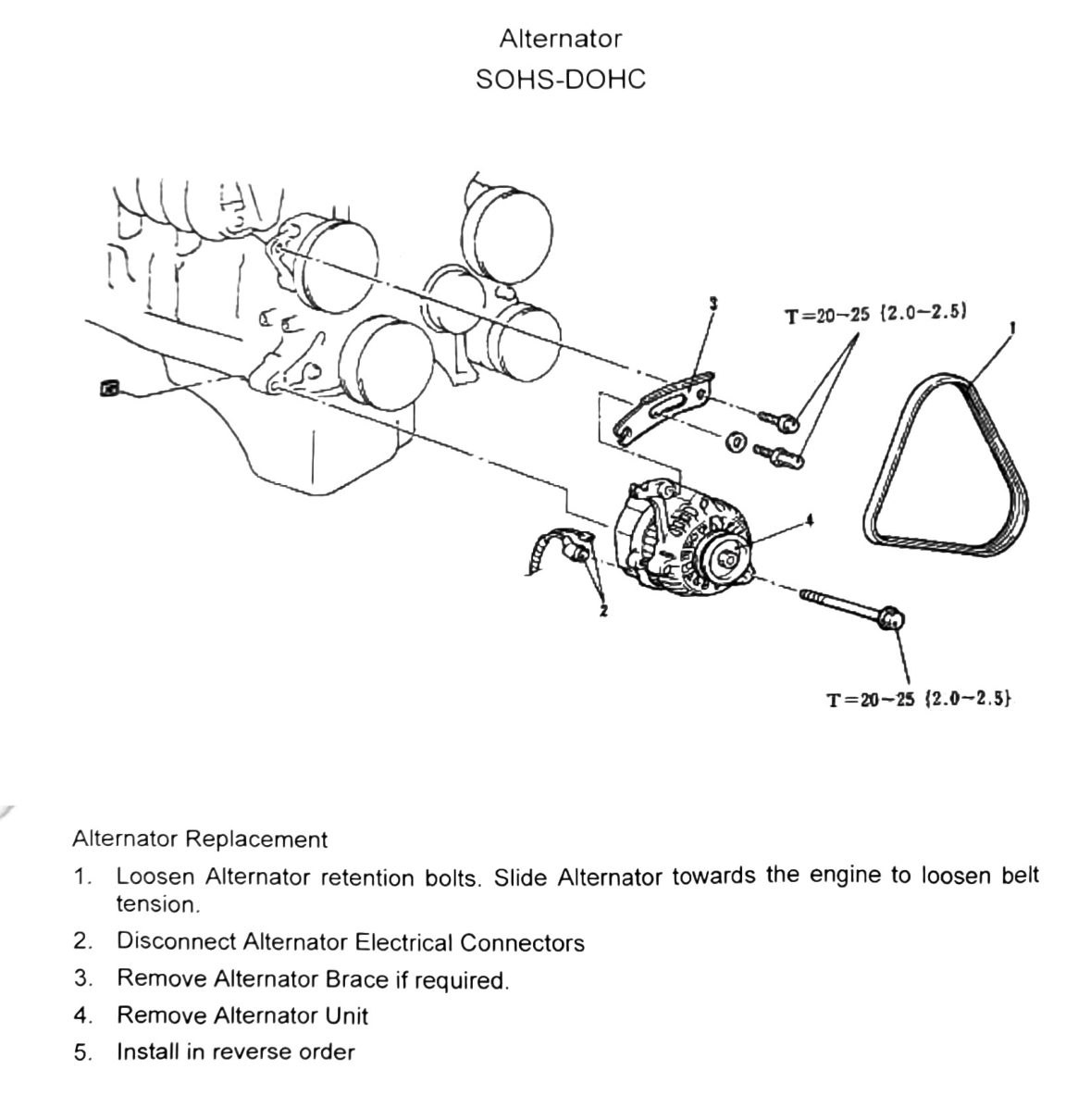
Alternator replacement (printed p.158)
- Loosen the alternator retention bolts. Slide the alternator toward the engine to loosen belt tension.
- Disconnect alternator electrical connectors.
- Remove the alternator brace, if required.
- Remove the alternator unit.
- Install in reverse order.
Torque specification
- Alternator retention/brace bolts: T = 20-25 N·m (2.0-2.5 kgf·m; 15-18 ft-lb)
(verify printed p.158) — the same “T=20-25 (2.0-2.5)” callout appears twice on this page (once near the top of the diagram, once at the bottom near the procedure). Treating both as the same alternator bolt spec restated, not as two distinct fasteners, but this is not fully confirmed against the figure.
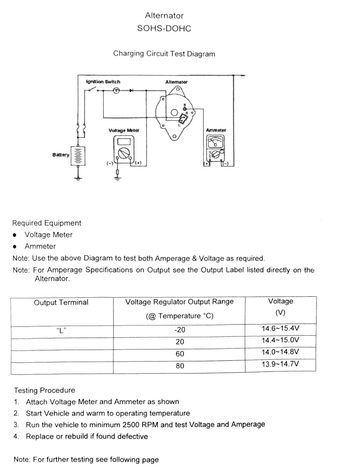
Charging circuit test (printed p.159)
Required equipment: voltage meter, ammeter.
Test circuit: Ignition switch → Alternator → Battery, with the voltage meter and ammeter connected as shown in the diagram (exact wiring/lead placement not recoverable from OCR text — see figure).
- Output terminal: “L”
- Note: for amperage output specifications, see the output label on the alternator itself (not listed on this page).
Voltage regulator output range
| Temperature (°C) | Temperature (°F) | Voltage (V) |
|---|---|---|
| -20 | -4 | 14.6-15.4V |
| 20 | 68 | 14.4-15.0V |
| 60 | 140 | 14.0-14.8V |
| 80 | 176 | 13.9-14.7V |
Testing procedure
- Attach the voltage meter and ammeter as shown.
- Start the vehicle and warm it to operating temperature.
- Run the vehicle to a minimum of 2500 RPM and test voltage and amperage.
- Replace or rebuild the alternator if found defective.
Oscilloscope test (printed p.160)
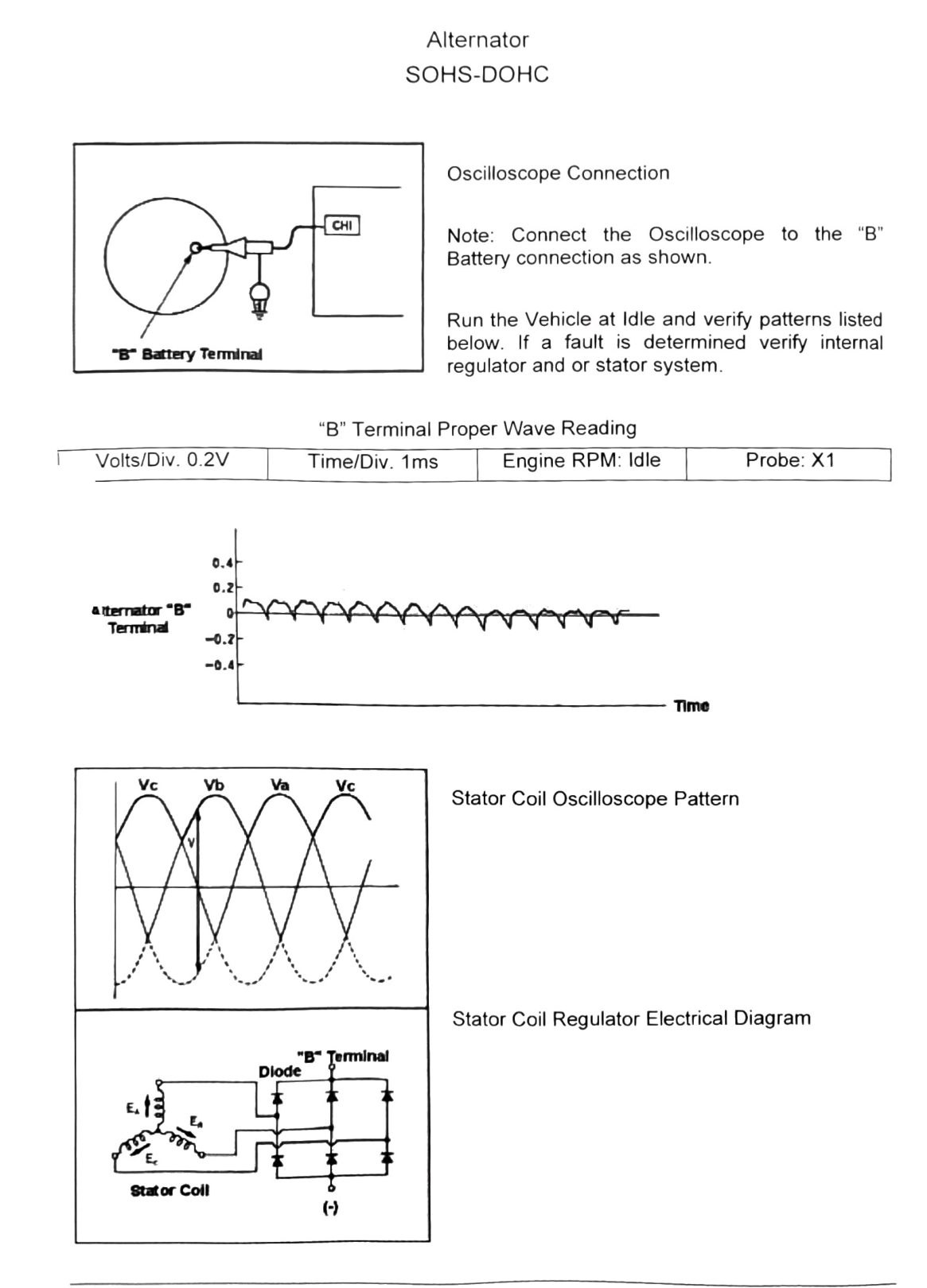
Connect the oscilloscope to the alternator “B” (battery) terminal as shown in the diagram. Run the vehicle at idle and verify the waveform pattern matches the reference pattern below. If a fault is found, verify the internal regulator and/or stator system.
- Volts/Div: 0.2V
- Time/Div: 1ms
- Engine RPM: Idle
- Probe: X1
- Test point: Alternator “B” terminal
(verify printed p.160) — the reference waveform itself (labeled with points “Va”, “Vb”, “Vc” in the OCR) is a diagram and did not survive as machine-readable text/values; only the test setup parameters above are recoverable. The page also references a “Stator Coil Oscilloscope Pattern” and a “Stator Coil Regulator Electrical Diagram” (with a diode symbol) — both are figures only, no additional numeric spec text recovered.