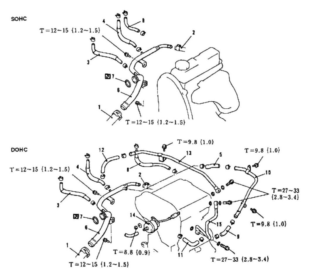
Water Hose Routing SOHC DOHC
The page shows two hose-routing diagrams side by side — one for SOHC (XR grade), one for DOHC turbo (VR grade — our truck) — sharing a single numbered parts list below them.
Hose routing & components
| # | Component | Valvetrain |
|---|---|---|
| 1 | Radiator Lower Hose | Both |
| 2 | Heater Hose | Both |
| 3 | Water Hose | Both |
| 4 | Water Hose | Both |
| 5 | Water Hose | DOHC |
| 6 | Water Inlet Pipe | Both |
| 7 | O-Ring | Both |
| 8 | Water Hose | Both |
| 9 | Water Hose | DOHC |
| 10 | Water Pipe Assy | DOHC |
| 11 | Water Hose | DOHC |
| 12 | Water Hose | DOHC |
| 13 | Water Pipe | Both |
| 14 | Waste Gate Actuator | DOHC (turbo component — see flag below) |
| 15 | Water Pipe | DOHC |
Items 5, 9, 10, 11, 12, and 15 are the ones our truck (DOHC turbo) actually needs; items 1-4, 6-8, and 13 are shared with the SOHC diagram.
(verified against scan p.153, 2026-08-30) — the printed parts list indeed does not tag item 14 “Waste Gate Actuator” with “DOHC”, but the diagrams settle it: item 14 appears only in the DOHC diagram (the actuator drawn at its center); the SOHC diagram contains only items 1, 2, 3, 4, 6, 7, and 8. The Waste Gate Actuator is DOHC/turbo-only as tabulated above.
Torque specifications
The following distinct torque values appear on this page: T = 12-15 N·m {1.2-1.5 kgf·m; 106-133 in-lb}, T = 9.8 N·m {1.0 kgf·m; 87 in-lb}, T = 27-33 N·m {2.8-3.4 kgf·m; 20-24 ft-lb}, and T = 8.8 N·m {0.9 kgf·m; 78 in-lb}.
(verified against scan p.153, 2026-08-30) — the leader lines were traced visually on the scan:
- T = 12-15 N·m {1.2-1.5} — appears twice on each diagram (SOHC and DOHC): the upper callout points to the clamp screw at the junction where Water Hoses 3/4 meet the engine-side fitting; the lower callout points to the attachment bolt on the Water Inlet Pipe (item 6), near item 1 (Radiator Lower Hose).
- T = 9.8 N·m {1.0} — DOHC diagram, three callouts: the bracket bolt on Water Pipe 13 (top center), and the upper and lower attachment bolts of the Water Pipe Assy DOHC (item 10, right side).
- T = 27-33 N·m {2.8-3.4} — DOHC diagram, two callouts covering three large hex screw-in joint fittings: a forked leader to the two joint fittings at the Water Pipe Assy (10) connections, and a third fitting at the Water Pipe DOHC (15) connection (bottom right).
- T = 8.8 N·m {0.9} — DOHC diagram, one callout: the small fastener immediately at the Waste Gate Actuator (item 14).
The stray OCR digits (“12”, “13”, “10”) were the diagram’s item-number labels, not torque data.
Note: Hoses must be replaced once removed on vehicles with over 50,000 km (31,069 mi).