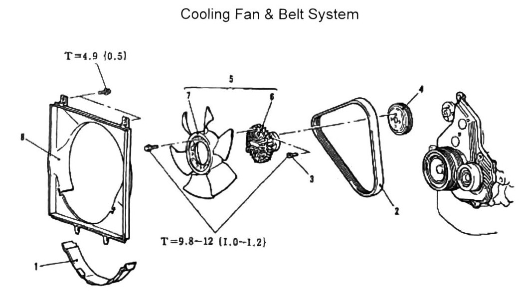
Cooling Fan & Belt System
Note: On A/C-equipped vehicles, remove the A/C Belt prior to disassembly.
Components & removal order
- Shroud Under Cover Unit
- Alternator Belt
- Clutch Fan Attachment Bolts
- Fan Pulley
- Cooling Fan & Clutch Assembly
- Clutch Assembly
- Fan
Torque specifications
| Fastener | Torque |
|---|---|
| Fan shroud attachment screw (top of shroud) | T = 4.9 N·m {0.5 kgf·m; 43 in-lb} |
| Clutch Fan Attachment Bolts (item 3) | T = 9.8-12 N·m {1.0-1.2 kgf·m; 87-106 in-lb} |
(verified against scan p.150, 2026-08-30) — the diagram’s leader lines are traceable in the scan: the T=4.9 {0.5} callout points to the small attachment screw at the top of the fan shroud, and the T=9.812 {1.01.2} callout forks to the two small bolts flanking the fan/clutch assembly, the right one carrying the diagram’s item-3 label (Clutch Fan Attachment Bolts). Neither torque points to the Fan Pulley (item 4).
Note: Fan belts must be replaced once removed on vehicles with over 80,000 km (49,710 mi).