Fuel Pump-Filter-Tank System
Fuel tank removal preparation (printed p.143)
- Remove rear driveshaft.
- Remove center exhaust piping.
Component removal
Explicitly numbered items recovered from OCR: 10. Fuel Tank Unit, 12. Fuel Tank Gage Sending Unit, 14. Fuel Pump Unit, 15. Valve Assembly, 16. Fuel Shut Off Valve.
Additional components named on these pages, exact sequence number not confirmed — (verify printed p.143-144):
- Parking Brake Cable Clamp Attachment Bolt (removed first, per procedure text)
- Filler Neck Protector
- Fuel Tank Cap
- Return Hose (plug before disconnecting)
- High Pressure Hose (plug before disconnecting)
- Vapor Hose
- Filler Hose
- Breather Hose
- Harness Connector
- Fuel Tank Gage Sending Unit Connector
- Fuel Pump Electrical Connector
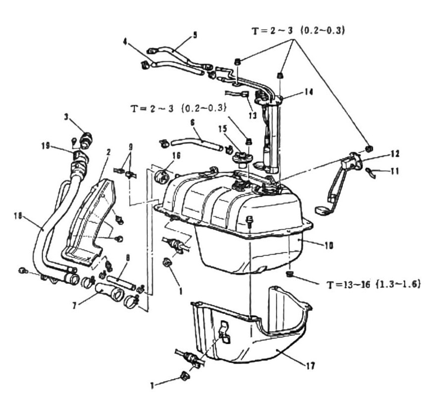
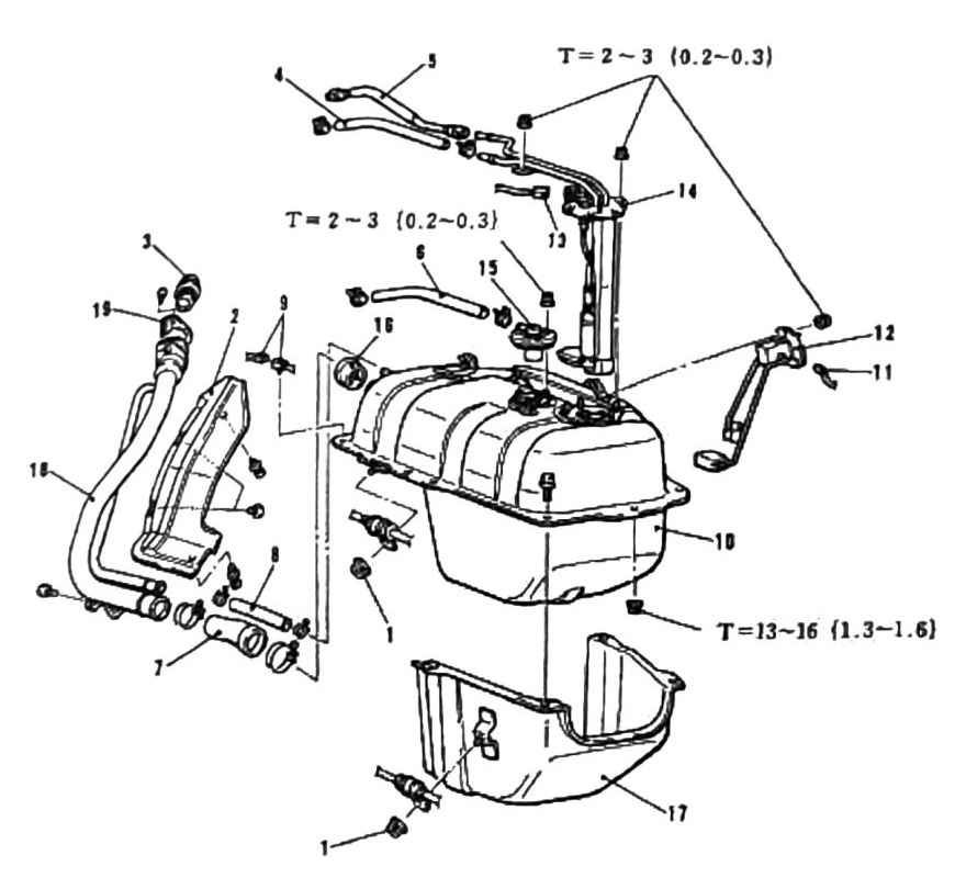
Filler hose installation
Note: when installing the fuel tank, proper hose alignment is essential for the filler hose — the hose is pre-shaped for a specific fit. Locate the hose mark and the tank alignment dot (“DOT”) and attach them aligned, as shown in the diagram.
Torque specifications
| Torque |
|---|
| 2-3 N·m (0.2-0.3 kgf·m; 18-27 in-lb) |
| 13-16 N·m (1.3-1.6 kgf·m; 115-142 in-lb) |
Fastener assignment for each value is not confirmed from OCR text alone — cross-reference the diagram. Both values recur consistently across printed p.143 and p.144 (same assembly, continued).
Final check (printed p.145)
(verify printed p.145) — this page’s text is almost entirely lost to OCR garble; the only recoverable fragment reads roughly “…possible leaks before driving vehicle,” consistent with a closing caution to check for fuel leaks after reassembly, but the full sentence is not recoverable. Do not treat this as a complete/verified procedure step.