Fuel Injector System
Injector testing procedure (printed p.137)
- Locate the injectors.
- Start the engine and warm to operating temperature.
- Use a stethoscope and listen to each injector for a “ticking” sound. If an injector is dead (no ticking), note its related cylinder. Test all injectors.
- Remove injector connectors and test connectivity as previously explained.
- Ohm range: 13-16 Ω @ 20°C (68°F). Check against ECU spec. Remove defective injectors for further bench testing.
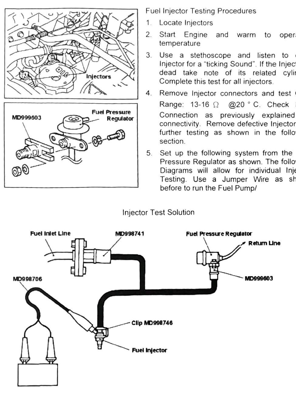
- Set up the individual-injector test rig from the fuel pressure regulator: fuel inlet line, hose adapter MD998741, injector test set MD998706 with clip MD998746, fuel injector, fuel pressure regulator, return line, adapter MD999603. Use a jumper wire (as in the Fuel Line Pressure Test) to run the fuel pump.
- Using adapter MD998706, apply direct (+)/(-) connectivity to engage the injector. If the injector fails to spray fuel, it must be replaced.
Note: if the vehicle has over 100,000 km (62,137 mi) and one injector has failed, all injectors in the set must be replaced together.
Component removal (printed p.138)
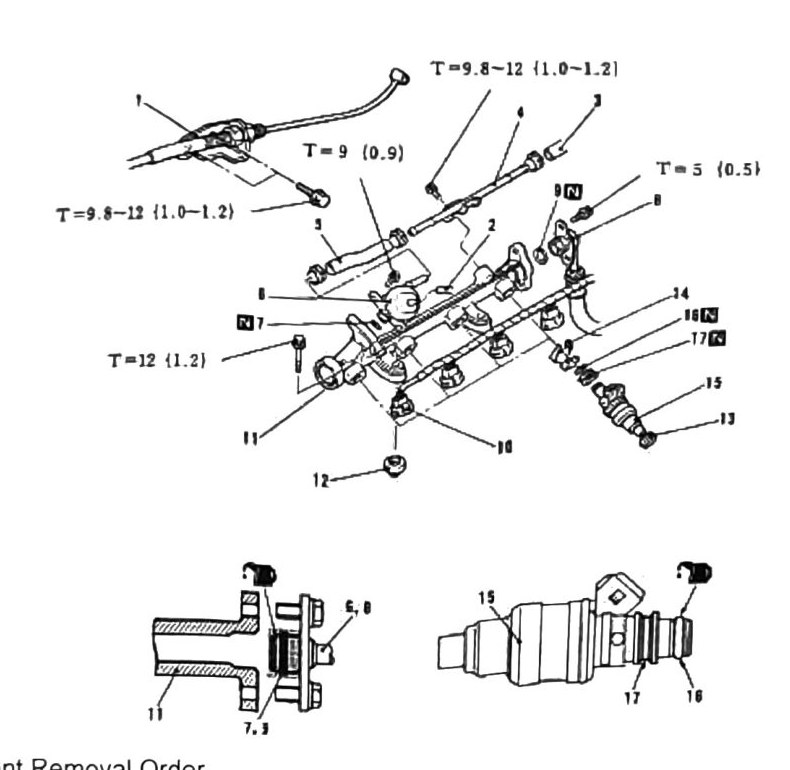
Component removal order, fuel rail assembly:
- Accelerator Cable
- Vacuum Hose
- Fuel Return Line
- Fuel Pipe
- Fuel Rubber Hose
- Fuel Pressure Regulator
- O-Ring
- Fuel Inlet High Pressure Hose
- O-Ring
- Injector Electrical Connector
- Fuel Rail
- Insulator Grommet
- Grommet
- Retainer
- Grommet
- O-Ring
- Grommet
(verify printed p.138) — items 1-9’s exact numbering is reconstructed from a scattered list of the digits 1 through 9 (each appearing exactly once near this item group) combined with the item names appearing in this same reading order; confidence is reasonable but not certain. Items 10-17 are directly numbered in the source and are high-confidence.
Torque values called out on this page’s diagram (fastener assignment for each not confirmed — verify printed p.138):
- 9.8-12 N·m (1.0-1.2 kgf·m; 87-106 in-lb)
- 9 N·m (0.9 kgf·m; 80 in-lb)
- 5 N·m (0.5 kgf·m; 44 in-lb)
- 12 N·m (1.2 kgf·m; 106 in-lb)
Note: when installing injectors, coat grommets and O-rings with engine oil before installation — failure to do so can impede proper sealing.