Engine ECU Connector Pin Guide
Engine ECU connector pin assignments, DOHC-turbo (52-pin) vs SOHC (46-pin). This entire section carries a blanket flag: the source table’s column alignment (which PIN # goes with which Circuit and Notes value) did not survive OCR/scan cleanly. Circuit names and voltage/note values below are transcribed in full and in their original reading order, but the exact PIN # pairing for each individual row is not confirmed — do not wire-test or replace a component based on a pin number below without checking a clean scan of printed p.126-129 first.
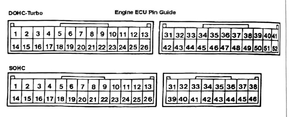
Circuits, in printed order (p.126)
| Circuit | Notes (as printed, unmatched to a specific pin #) |
|---|---|
| No.1 & No.3 Fuel Injector | Range 11-14V @3000RPM |
| No.2 & No.4 Fuel Injector | Voltage Variation Limit: 0.3-3.0V |
| No.1, No.4 Ignition Coil PWR Resistor | Engine OFF, Servo Closed: PWR Range 0-6V |
| No.2, No.3 Ignition Coil PWR Resistor | — |
| ISC Servo (A) | — |
| ISC Servo (B) | — |
| ISC Servo (C) | — |
| ISC Servo (D) | 0-3V |
| Engine Warning Lamp | 12-14V |
| Exhaust Over Temp Warning Lamp | A/C OFF: 0-3V |
| Waste Gate Solenoid Valve | A/C ON: 12-14V |
| A/C Switch | — |
(verify printed p.126) — pin numbers observed on this page, in printed reading order (not confirmed to correspond row-for-row with the circuits above): 1, 14, 2, 15, 4, 17, 5, 18, 8, 6, 7, 9.
Circuits, in printed order (p.127, “Continued”)
| Circuit | Notes (as printed) |
|---|---|
| ECU PWR Switch | Engine OFF: 0-3V |
| ABS-ECU Signal (M/T) | Engine ON: 12-14V |
| Power | Idle to 60 KPH: 12-14V; Over 60 KPH: 0-3V |
| Backup Power Circuit | PWR ON: 12-14V |
| Sensor PWR Circuit | IGN Switch OFF: 12V; IGN Switch ON: 4.5-5.5V |
| Earth (-) Negative Ground | 0 Volts |
| Sensor (-) Negative Ground | 0 Volts |
| Control Relay (Fuel Pump) | ING ON: 12-14V; Engine Idle: 0-3V |
| Control Relay Power | ING Switch ON: 0-3V; ING Switch OFF: 12V |
| A/C Relay | Battery PWR, or 6V-0-3V |
| Fuel Pressure Solenoid Valve | ING ON: 12V |
| Starter Switch | Cranking to Idle within 2 min: 0-3V |
| P/S Oil Pressure Switch | Cranking: 8V+; Idle: 12V |
| A/C Cut Off Switch (M/T) | Idle Turning: 0-3V |
| — (unlabeled row) | Accelerator Pedal Push: 0-3V |
| Water Temp Sensor | ING ON, Full Acceleration: 12V; 0°C (32°F) 3.2-3.8V; 20°C (68°F) 2.3-2.9V; 40°C (104°F) 1.3-1.9V; 80°C (176°F) 0.5-2.8V |
(verify printed p.127) — pin numbers observed on this page, in printed reading order: 11, 22, 25, 22, 12, 24, 25, 31, 46, 39, 13, 26, 19, 40, 52, 45, 21, 20, 20, 22, 22, 8, 23, 11, 1, 23, 44, 32. This page is the most heavily scrambled in the chapter; row-level circuit/pin/voltage correspondence is not recoverable from this OCR pass.
Circuits, in printed order (p.128, “Continued”)
| Circuit | Notes (as printed) |
|---|---|
| Boost Sensor | ING SW ON; Altitude 0m: 3.7-4.3V; Altitude 1200m: 3.2-3.8V; @Idle: 0.9-1.9V |
| Throttle Position Sensor (TPS) | ING SW ON; @Idle 0.4-0.9V; Full Throttle 4.5-5.5V |
| Vehicle Speed Sensor | ING ON: 0-5V |
| Idle Switch | Idle: 0-1V; Off Idle: 4V+ |
| Crankshaft Sensor | Cranking: 0.4-4.0V; Idle: 1.5-2.5V |
| Neutral Safety Switch A/T | P or N Position: 0-3V; D, 2, L, R: 12V |
| Ignition Switch | OFF: 0-3V; ON: 12-14V |
| Exhaust High Temp Sensor (+) | 10-15 mV |
| Exhaust High Temp Sensor (-) | 2.0-2.9V |
| A/C Thermo Sensor @25°C (77°F) | ING Switch ON; 0°C (32°F) 3.2-3.8V; 20°C (68°F) 2.3-2.9V; 40°C (104°F) 1.5-2.1V; 80°C (176°F) 0.4-1.0V |
| Exhaust Temp Sensor | Engine RPM 2000+: 0-0.8V |
| Oxygen Sensor | Idle: 0V+ |
| Knock Sensor | ING Switch ON; Earth: 0-1V; PWR: 4.5-5.5V |
| Timing Pickup Sensor | — |
(verify printed p.128) — pin numbers observed on this page, in printed reading order: 33, 41, 34, 35, 36, 43, 43, 21, 21, 37, 24, 40, 32, 41, 31, 42, 34, 43, 35, 44, 42, 45, 45, 46, 39, 47, 48, 38 (one row also shows ”—” for a not-applicable SOHC pin). Row-level correspondence not recoverable.
Circuits, in printed order (p.129, “Continued”)
| Circuit | Notes (as printed) |
|---|---|
| Diagnostic Control | ING Switch ON |
| Tachometer | Earth: 0-1V; PWR: 4.5-5.5V; Cranking: 0-5V |
| Diagnostic Output | ING Switch ON: 0-5V |
(verify printed p.129) — pin numbers observed on this page, in printed reading order: 49, 37, 55, 50, 33, 51, 36.
See also: Diagnostic Harness Pin Guide (the harness-side ohm-test version of this same pin map, somewhat better preserved by OCR), MUT Hand Held Diagnostics & ECU Troubleshooting Codes.