Crankshaft & Cylinder Block
Applies to all engine variants (SOHC and DOHC) — the manual heads this section “Crankshaft & Cylinder Block: All.” Flywheel/drive-plate hardware differs by transmission (manual = flywheel, automatic = drive plate); our truck (3-speed automatic 3A/T) uses the drive plate, not the flywheel.
Component removal order
- Flywheel bolts (5M/T)
- Flywheel (5M/T)
- Drive plate bolt (3A/T — our truck)
- Outer plate (3A/T)
- Drive plate (3A/T — our truck)
- Rear plate
- Bell housing cover
- Oil seal case
- Oil seal
- Bearing cap bolt
- Bearing cap
- Lower crankshaft bearing
- Crankshaft
- Thrust bearing
- Upper crankshaft bearing
- Cylinder block
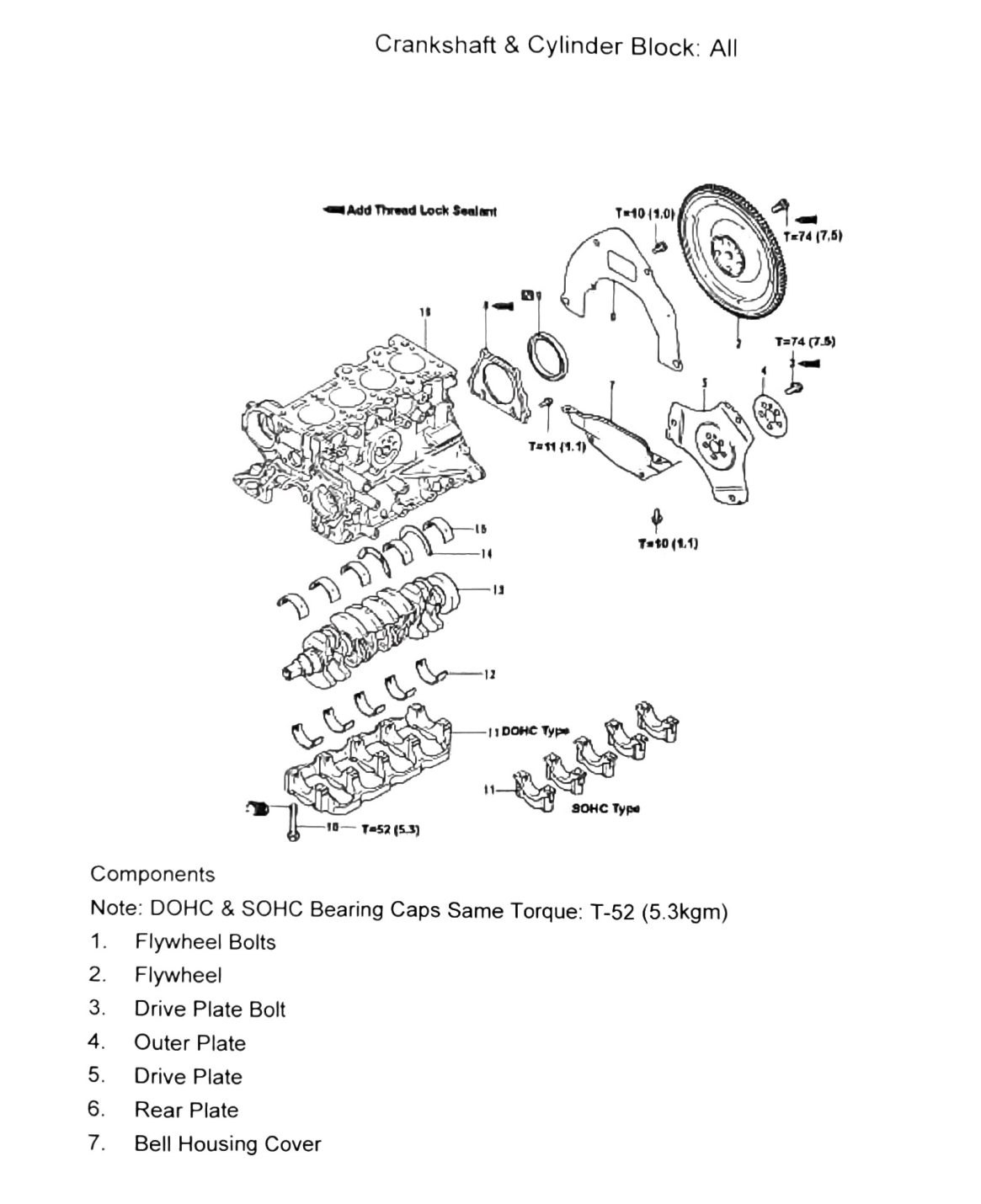
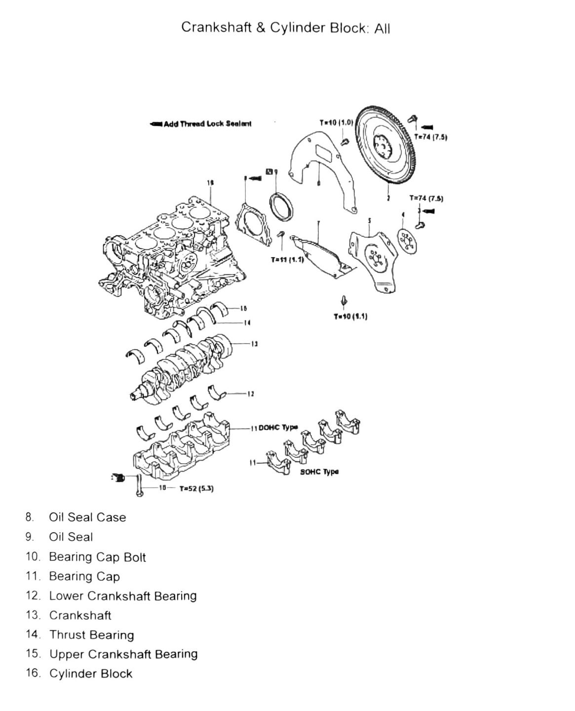
Main bearing cap torque — SOHC vs DOHC
Note (as printed): “DOHC & SOHC Bearing Caps Same Torque: T=52 (5.3kgm)”
Torque: 52±2 N·m (5.3 kgf·m; 38±1.5 ft-lb) — same for both SOHC and DOHC. This is confirmed by a clean maintenance-note restatement later in this section (“Torque: 52±2 Nm”); used with confidence.
Flywheel / drive plate bolt torques (as scanned)
| Value as scanned |
|---|
| T=10 (1.0; 89 in-lb) |
| T=74 (7.5; 55 ft-lb) — appears twice |
| T=11 (1.1; 97 in-lb) |
| T=10 (1.1) — internally inconsistent (10 N·m ≠ 1.1 kgf·m); likely OCR duplication/garble of one of the above |
(verify printed p.108-109) — which of these values applies to flywheel bolts vs. drive plate bolts vs. bell housing cover screws could not be mapped from the OCR. Given our truck runs the 3A/T drive plate, confirm the drive plate bolt torque specifically before reassembly — do not assume it’s the largest (74/7.5) figure without checking the printed diagram; on many similar engines the higher torque is the flywheel/drive-plate-to-crankshaft bolt, but this manual’s own diagram text is too garbled to confirm which balloon-numbered fastener that applies to.
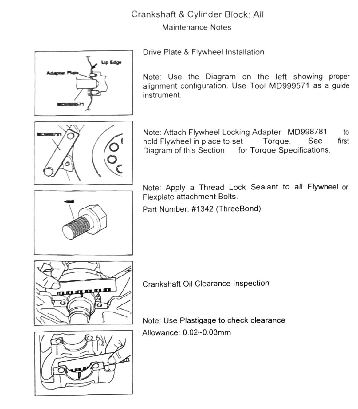
Note: Apply thread lock sealant to all flywheel or flexplate attachment bolts. Part number: #1342 (ThreeBond).
Use tool MD999571 as an alignment guide for drive plate & flywheel installation. Use flywheel locking adapter MD998781 to hold the flywheel in place when setting torque.
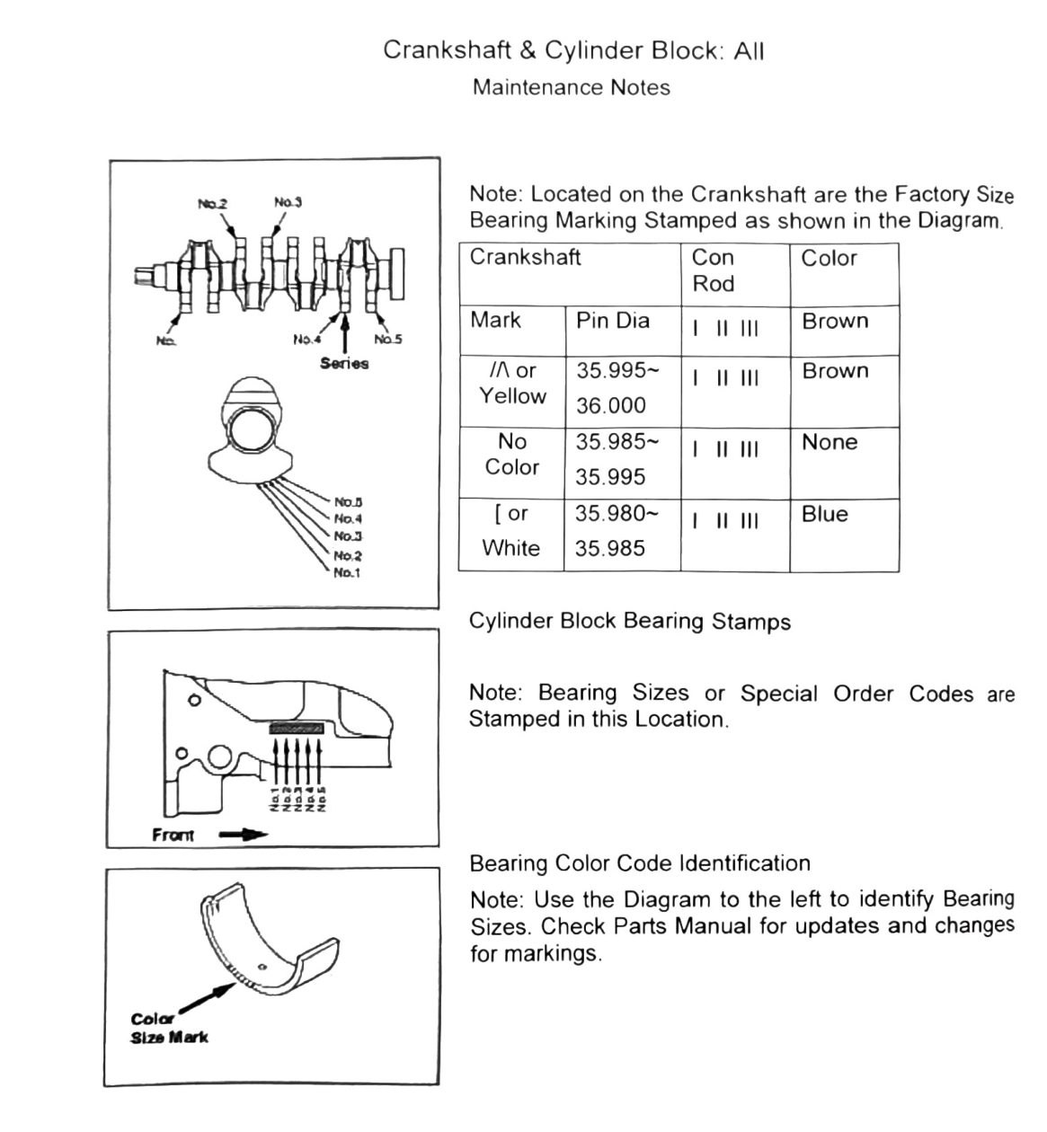
Bearing size marks
Note: Factory size bearing markings are stamped on the crankshaft, as shown in the diagram.
(verify printed p.110) — same issue as the connecting rod bearing table in 40-pistons-connecting-rods.md: color-code-to-diameter mapping did not survive OCR with confidence. Do not select a main bearing from color alone without checking a clean scan or the Parts Manual.
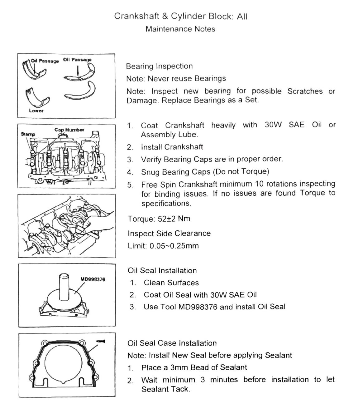
Crankshaft installation & inspection
- Coat crankshaft heavily with 30W SAE oil or assembly lube.
- Install crankshaft.
- Verify bearing caps are in proper order.
- Snug bearing caps — do not torque yet.
- Free-spin crankshaft a minimum of 10 rotations, inspecting for binding. If no issues are found, torque to specification.
Torque: 52±2 N·m (38±1.5 ft-lb) (matches the note on printed p.108 above — confirmed).
Side clearance limit: 0.05-0.25mm (0.002–0.010in)
Oil seal / oil seal case installation
- Clean surfaces.
- Coat oil seal with 30W SAE oil.
- Use tool MD998376 to install the oil seal.
Oil seal case: install new seal before applying sealant; place a 3mm (0.118in) bead of sealant; wait a minimum of 3 minutes before installation to let sealant tack.
Crankshaft oil clearance inspection
Use Plastigage to check clearance.
Allowance: 0.02-0.03mm (0.001in) — matches the Engine Specifications table’s Crankshaft Journal Oil Clearance figure; confirmed. (This inspection is on printed p.112, alongside the drive plate & flywheel installation notes above.)
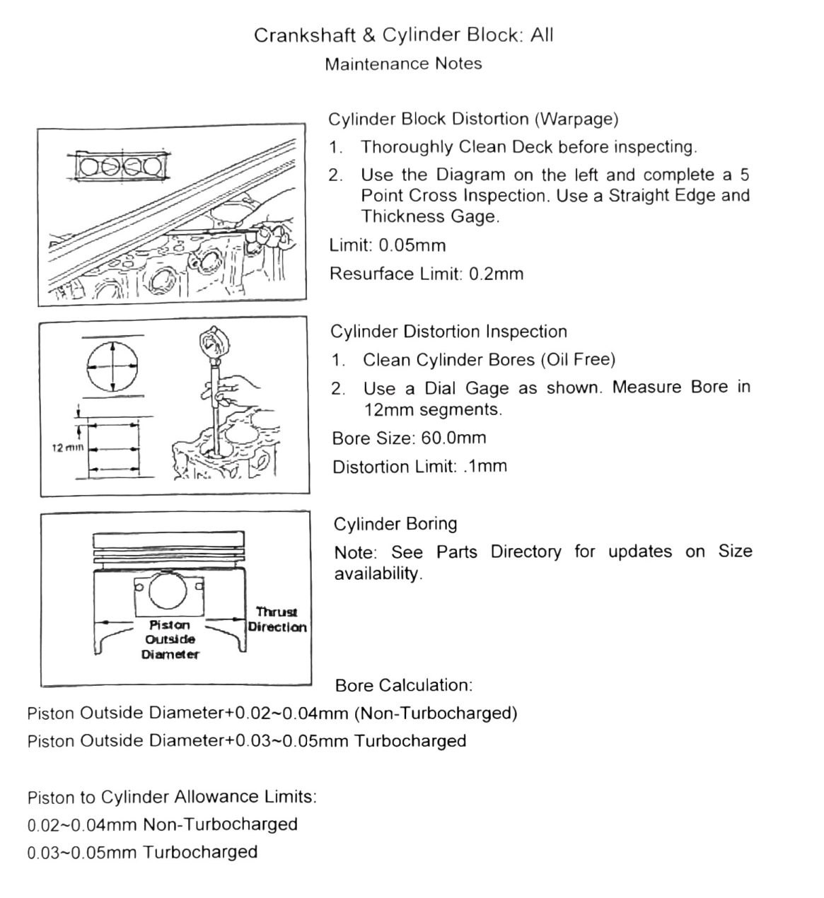
Cylinder block distortion (warpage)
- Thoroughly clean deck before inspecting.
- Use a straight edge and thickness gauge, complete a 5-point cross inspection.
| Item | Value |
|---|---|
| Distortion limit | 0.05mm (0.002in) |
| Resurface limit | 0.2mm (0.008in) |
Cylinder bore inspection & boring
- Clean cylinder bores (oil-free).
- Use a dial gauge, measure bore in 12mm segments.
| Item | Value |
|---|---|
| Bore size (STD) | 60.0mm (2.362in) |
| Distortion limit | 0.1mm (0.004in) (verify printed p.113) |
(verify printed p.113) — this maintenance-note figure (“Distortion Limit: .1mm”) conflicts with the Engine Specifications table’s “Cylinder Distortion Limit: Below 0.01mm” (see 34-engine-specifications.md) — a full order-of-magnitude difference. Confirm against a clean scan before using either figure.
Cylinder boring calculation — SOHC vs DOHC (turbo)
| Configuration | Bore calculation |
|---|---|
| Non-turbo (SOHC) | Piston OD + 0.02-0.04mm (0.001–0.002in) |
| Turbo (DOHC — our truck) | Piston OD + 0.03-0.05mm (0.001–0.002in) |
Piston-to-cylinder allowance limits — SOHC vs DOHC (turbo)
| Configuration | Clearance |
|---|---|
| Non-turbo (SOHC) | 0.02-0.04mm (0.001–0.002in) |
| Turbo (DOHC — our truck) | 0.03-0.05mm (0.001–0.002in) |
These match the Engine Specifications table exactly (see 34-engine-specifications.md) and are used with confidence. Our 4A30 DOHC turbo uses 0.03-0.05mm, not the SOHC figure.