Pistons & Connecting Rods
Applies to all engine variants (SOHC and DOHC) — the manual heads this section “Pistons & Connecting Rods: All.”
Component removal order
- Nut
- Connecting rod cap
- Connecting rod bearing
- Piston & connecting rod
- Connecting rod bearing
- Piston ring No.1
- Piston ring No.2
- Oil ring
- Piston pin
- Piston
- Connecting rod
- Bolt
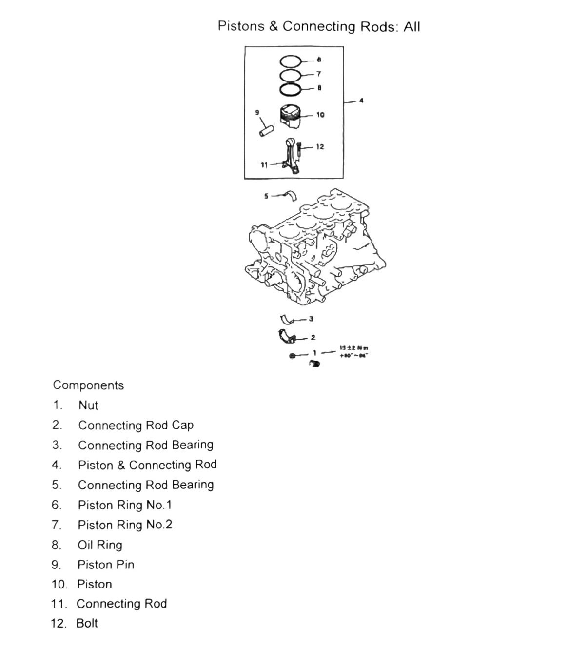
Connecting rod bolt torque (as scanned)
The diagram shows a fragment: “13±2 4m” / “+80°-84°” next to item 12 (bolt).
(verify printed p.102) — this reads as a possible torque-to-yield (TTY) spec: an initial torque figure (garbled — could be 13±2 N·m or similar) followed by an additional rotation angle of 80°-84°. Neither the base torque number nor the angle range should be treated as confirmed; the OCR could not cleanly separate digits from the surrounding balloon numbers (“12,” “1,” “26,” “11”). Do not torque connecting rod bolts to a guessed value — confirm against a clean scan before overhaul.
Piston pin removal
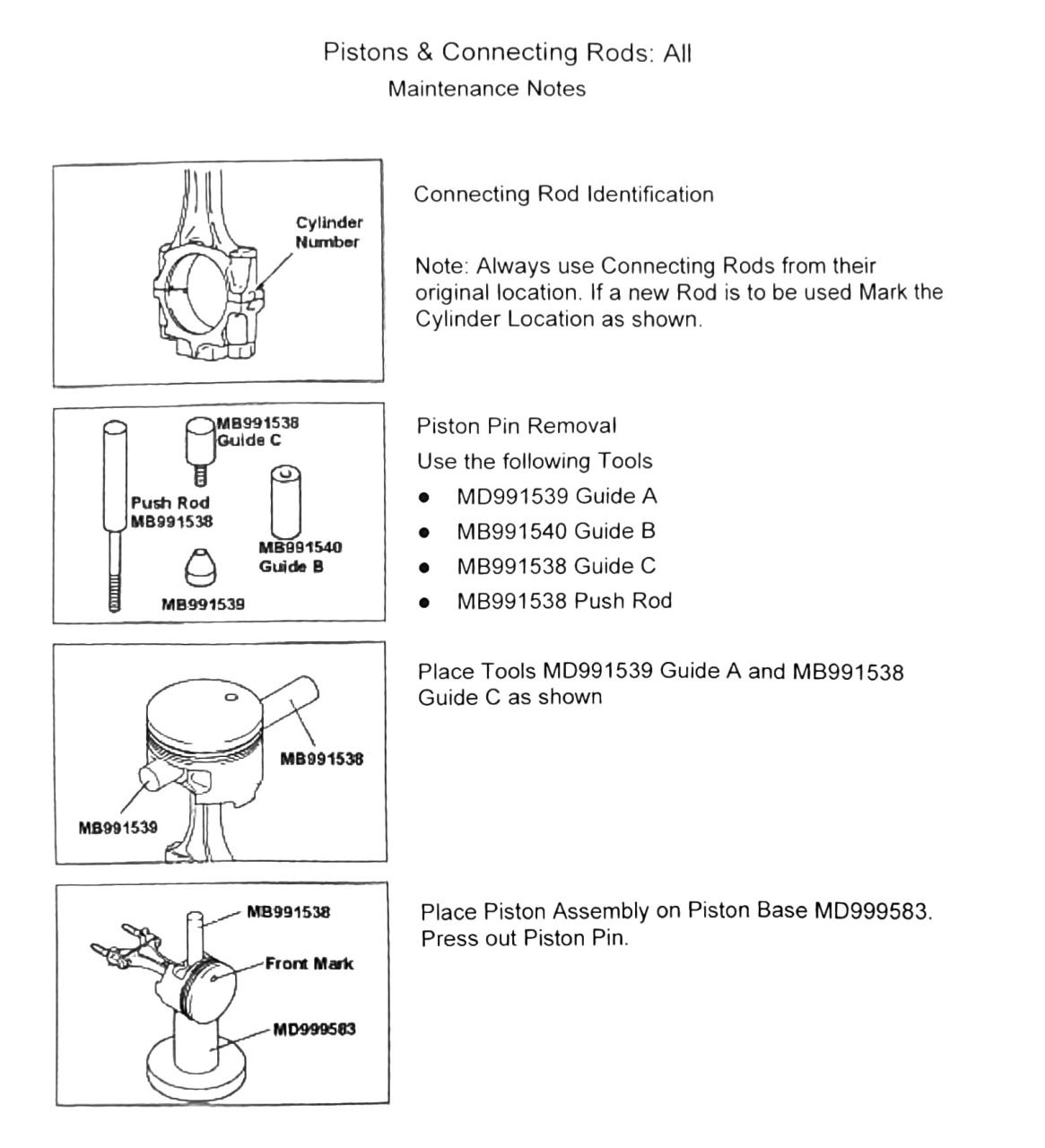
Tools required:
- MD991539 — Guide A
- MB991540 — Guide B
- MB991538 — Guide C / push rod
Procedure: place tools Guide A and Guide C as shown, place the piston assembly on piston base MD999583, and press out the piston pin.
Note: Always use connecting rods from their original cylinder location. If a new rod is used, mark the cylinder location as shown.
Piston pin installation
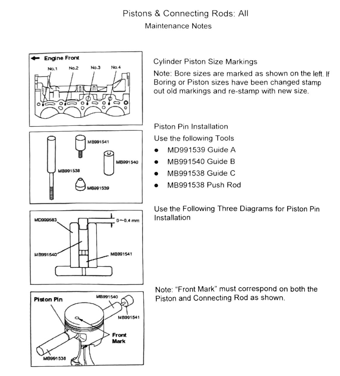
Same tool set as removal (Guide A/B/C, push rod).
Note: The “Front Mark” must correspond on both the piston and connecting rod as shown.
Note: Cylinder bore/piston size markings are stamped on the piston. If boring or piston sizes have changed, stamp out old markings and re-stamp with the new size.
Required press force: 4900-10,780 N (matches the Engine Specifications table — confirmed).
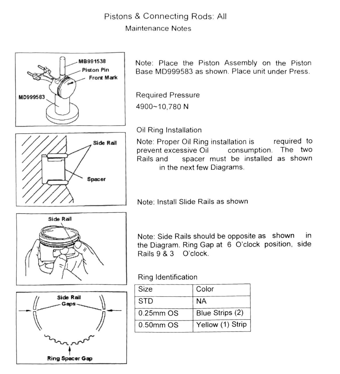
Oil ring installation
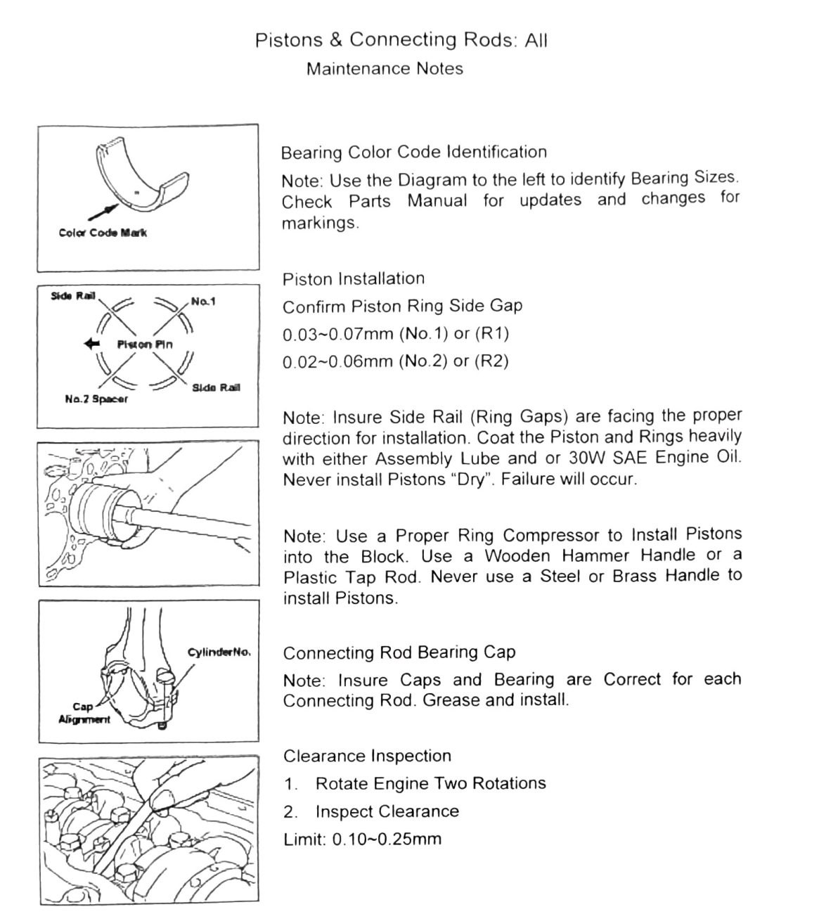
Note: Proper oil ring installation is required to prevent excessive oil consumption. The two side rails and spacer must be installed as shown.
Note: Side rails should be opposite as shown in the diagram — ring gap at the 6 o’clock position, side rails at 9 & 3 o’clock.
Ring identification (oil ring side rail)
| Size | Color mark |
|---|---|
| STD | N/A (no mark) |
| 0.25mm OS | Blue stripes (2) |
| 0.50mm OS | Yellow stripe (1) |
Ring identification (compression rings)
| Size | Mark |
|---|---|
| STD | No mark |
| 0.25mm OS | ”25” |
| 0.50mm OS | ”50” |
Ring position codes: 1R = top ring, 2R = second ring.
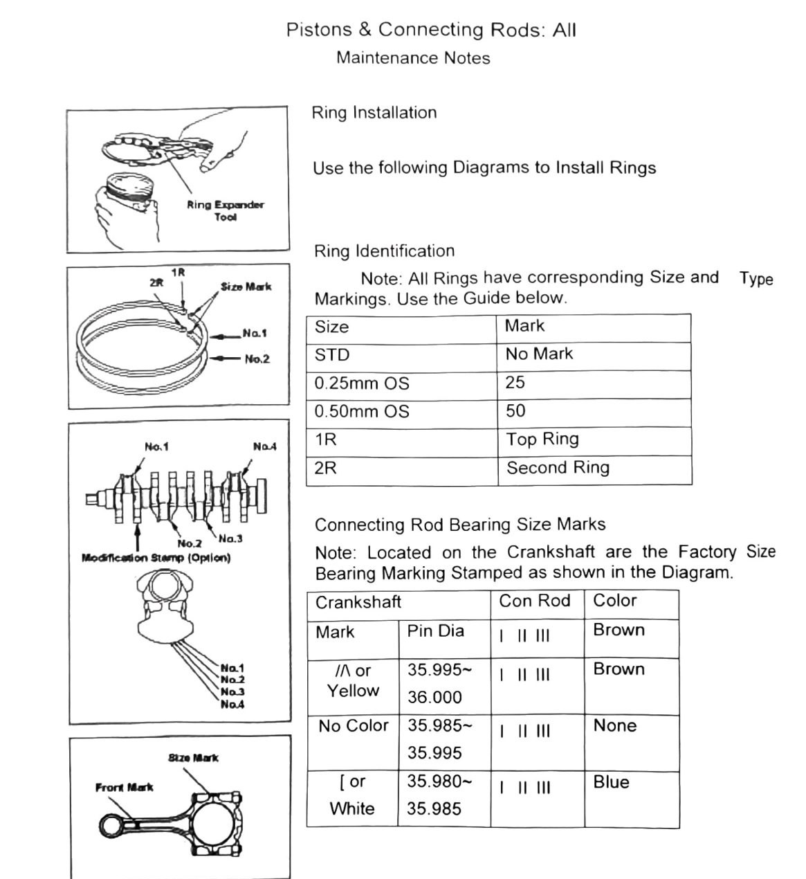
Connecting rod bearing size marks
Note: Factory size bearing markings are stamped on the crankshaft, as shown in the diagram. Check the Parts Manual for updates and changes to markings.
(verify printed p.106) — the bearing color-code table lost its row/column alignment in OCR. Recovered fragments suggest three size bands identified by tick-mark count (|, ||, |||) crossed with a color (Brown, No Color, Blue/White), against three connecting-rod pin diameter ranges:
| Pin diameter range (as scanned) |
|---|
| 35.995-36.000mm (1.4171–1.4173in) |
| 35.985-35.995mm (1.4167–1.4171in) |
| 35.980-35.985mm (1.4165–1.4167in) |
Do not assign a specific color/mark combination to a specific pin-diameter range from this table — the OCR order does not reliably preserve which color goes with which range. Confirm against a clean scan or the Parts Manual before selecting a replacement bearing.
Piston/ring installation to block
Note: Ensure side rail (ring gaps) are facing the proper direction for installation. Coat the piston and rings heavily with assembly lube and/or 30W SAE engine oil. Never install pistons “dry” — failure will occur.
Note: Use a proper ring compressor to install pistons into the block. Use a wooden hammer handle or plastic tap rod. Never use a steel or brass handle to install pistons.
Piston ring side gap (confirm before installation):
| Ring | Gap |
|---|---|
| No.1 (R1) | 0.03-0.07mm (0.001–0.003in) |
| No.2 (R2) | 0.02-0.06mm (0.001–0.002in) |
Connecting rod bearing cap
Note: Ensure caps and bearings are correct for each connecting rod. Grease and install.
Clearance inspection
- Rotate engine two full rotations.
- Inspect clearance.
Limit: 0.10-0.25mm (0.004–0.010in) — matches the Engine Specifications table’s Connecting Rod (Big End) Clearance figure; confirmed.