Cylinder Head Gasket Replacement (DOHC)
DOHC Turbo procedure — our truck’s configuration. It follows the same overall pattern as the SOHC job (Section 21) but has additional turbo-related connectors and an intercooler removal step, plus hydraulic lifters instead of an adjustable valvetrain.
Note: remove or disconnect the following before proceeding:
- Drain engine coolant.
- Remove air cleaner assembly.
- Remove intercooler.
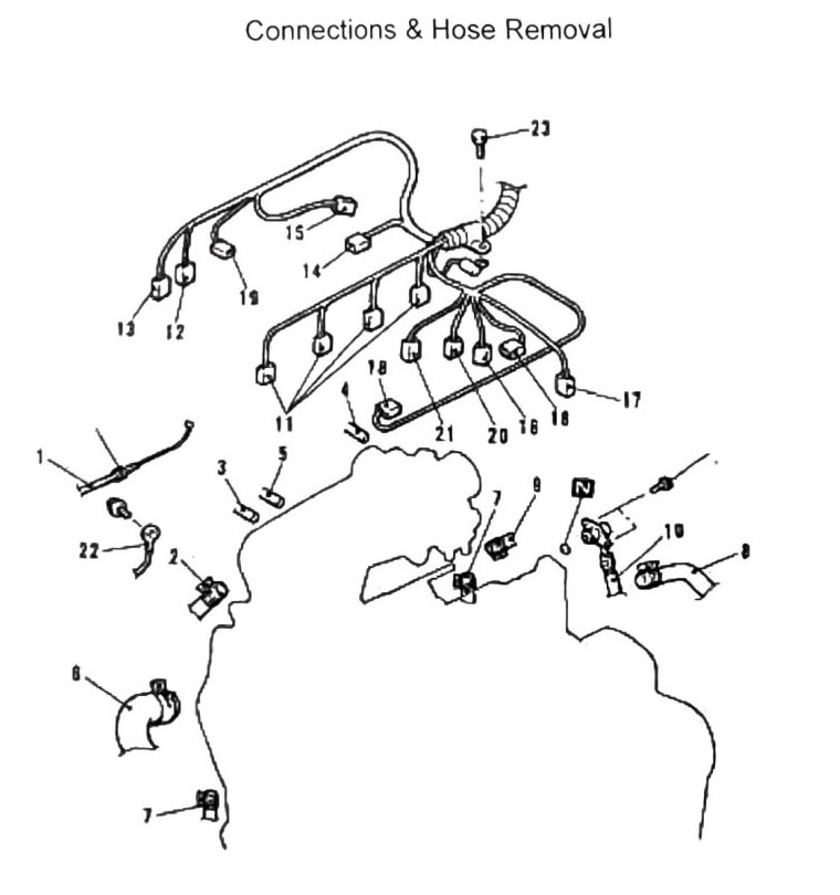
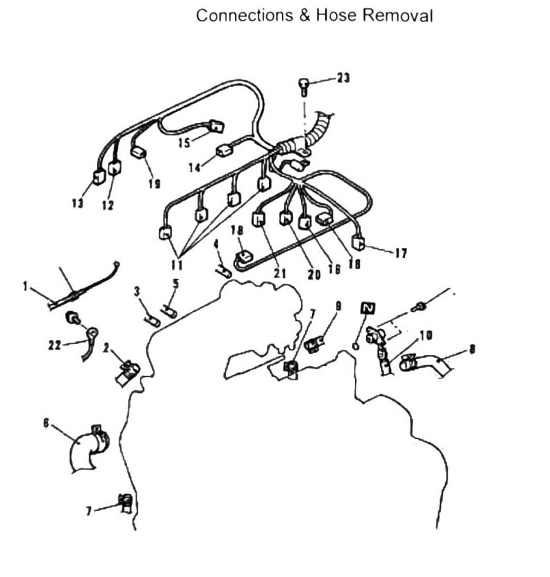
Connections & hose removal, in order
- Accelerator cable
- Brake booster vacuum hose
- Vacuum hose
- Canister vacuum hose
- Boost sensor (vacuum hose)
- Radiator upper hose
- Water hose
- Heater hose
- Fuel return hose
- Fuel inlet hose
- Fuel injector connectors
- Water temperature sensor connector
- Water temperature gauge sensor
- ISC solenoid valve connector
- TPS connector
- Oxygen (O2) sensor connector
- Crank position sensor connector
- Ignition coil connectors
- Exhaust temperature connector — DOHC turbo-specific, not present on the SOHC list
- Knock sensor connector — DOHC turbo-specific, not present on the SOHC list
- Fuel pressure solenoid valve connector — DOHC turbo-specific, not present on the SOHC list
- Ground cable (–)
- Harness retainer bolt
Mechanical component removal
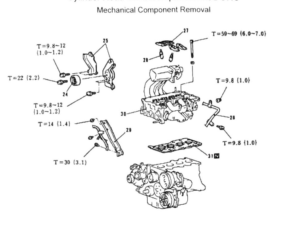
Remove the following as covered in previous sections: timing belt, valve cover assembly, exhaust head pipe.
Continued component removal, in order:
- Idler pulley
- Timing belt rear cover
- Water pipe
- Rocker arms
- Hydraulic lifters (tappets) — DOHC-specific; SOHC uses adjustable rocker-arm valve lash instead (see Section 8)
- Intake manifold bracket
- Cylinder head assembly
- Cylinder head gasket
- Install in reverse order
Note: never reuse gaskets or engine coolant.
Torque values
| Fastener | Torque |
|---|---|
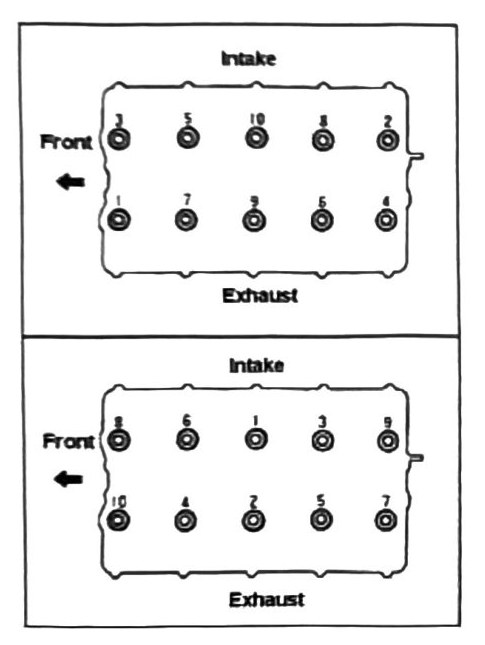
| Cylinder head bolts | 59–69 N·m (6.0–7.0 kgf·m; 44–51 ft-lb), torqued cold, in the specified installation pattern (confirmed clean on both printed p.55 and p.56 for this DOHC section — no conflict here, unlike the SOHC page) |
(verify printed p.55) — additional torque callouts on the mechanical-removal diagram could not be confidently matched to specific fasteners: 9.8–12 N·m (1.0–1.2 kgf·m; 87–106 in-lb) (appears twice), 9.8 N·m (1.0 kgf·m; 87 in-lb) (appears twice), 22 N·m (2.2 kgf·m; 16 ft-lb), 14 N·m (1.4 kgf·m; 124 in-lb), and 30 N·m (3.1 kgf·m; 22 ft-lb). Confirm each against the printed diagram before use.