Cylinder Head Gasket Replacement (SOHC)
Note: remove or disconnect the following before proceeding:
- Drain engine coolant.
- Remove air cleaner assembly.
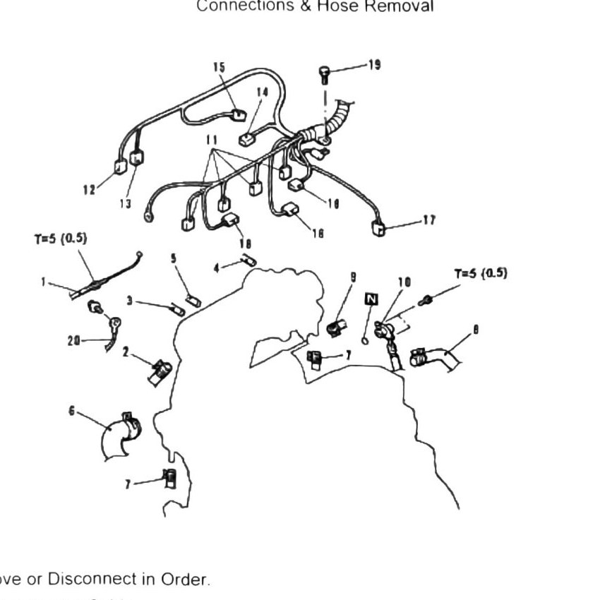
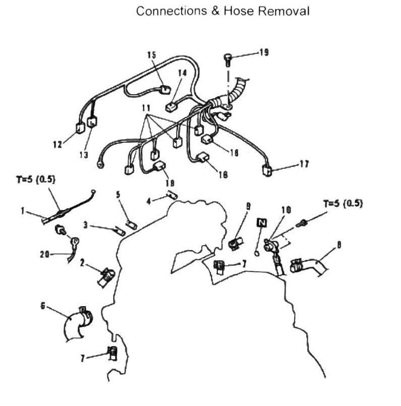
Connections & hose removal, in order
- Accelerator cable
- Brake booster vacuum hose
- Vacuum hose
- Canister vacuum hose
- Boost sensor vacuum hose
- Radiator upper hose
- Water hose
- Heater hose
- Fuel return hose
- Fuel inlet hose
- Fuel injector connectors
- Water temperature sensor connector
- Water temperature gauge sensor
- ISC solenoid valve connector
- TPS connector (A/T vehicle)
- Oxygen (O2) sensor connector
- Crank position sensor connector
- Ignition coil connectors
- Harness clamp attachment bolt
- Ground cable (–)
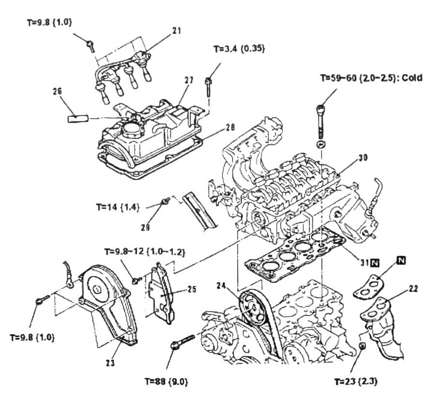
Mechanical component removal, in order
- Ignition coils and spark plugs
- Exhaust header pipe
- Timing belt upper cover
- Camshaft sprocket
- Timing belt cover
- PCV hose
- Valve cover
- Valve cover gasket
- Intake manifold bracket
- Cylinder head
- Cylinder head gasket
Note: install in reverse order. Never reuse gaskets.
Installation notes
Use tools MB990767 and MD998719 to stabilize the camshaft sprocket during removal and installation.
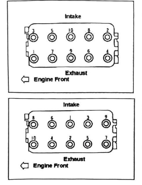
Follow the cylinder head bolt removal pattern (reverse of the installation/torque order pattern shown in the diagram — outward from center, engine front as reference).
Torque values
| Fastener | Torque |
|---|---|
| Cylinder head bolts | 59–69 N·m (6.0–7.0 kgf·m; 44–51 ft-lb), torqued cold, in the specified installation pattern |
(verify printed p.51 vs p.52) — a garbled partial figure on printed p.51 reads “T-59-60 (2.0-2.5): Cold,” which conflicts with the clean, explicit restatement on printed p.52: “Torque 59-69 (6.0~7.0) Torque Cold.” The p.52 figure above is used here as authoritative since it is unambiguous, but confirm against the printed page.
(verify printed p.51) — additional torque callouts on the mechanical-removal diagram could not be confidently matched to specific fasteners: 9.8 N·m (1.0 kgf·m; 87 in-lb) (appears twice), 3.4 N·m (0.35 kgf·m; 30 in-lb), 14 N·m (1.4 kgf·m; 124 in-lb), 9.8–12 N·m (1.0–1.2 kgf·m; 87–106 in-lb), 88 N·m (9.0 kgf·m; 65 ft-lb), and 23 N·m (2.3 kgf·m; 17 ft-lb). Confirm each against the printed diagram before use.