Timing Belt Removal & Installation (DOHC)
This is the DOHC Turbo procedure — our truck’s configuration. It differs from the SOHC procedure (Section 16) in having an additional idler pulley and separate intake/exhaust camshaft sprockets, each with their own triangle timing marks.
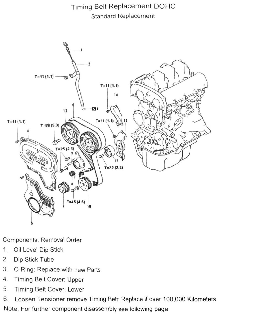
Component removal order
- Oil level dip stick
- Dip stick tube
- O-ring (remove and discard — replace with new part)
- Timing belt cover, upper
- Timing belt cover, lower
- Loosen tensioner and remove timing belt — replace if over 100,000km (62,137mi)
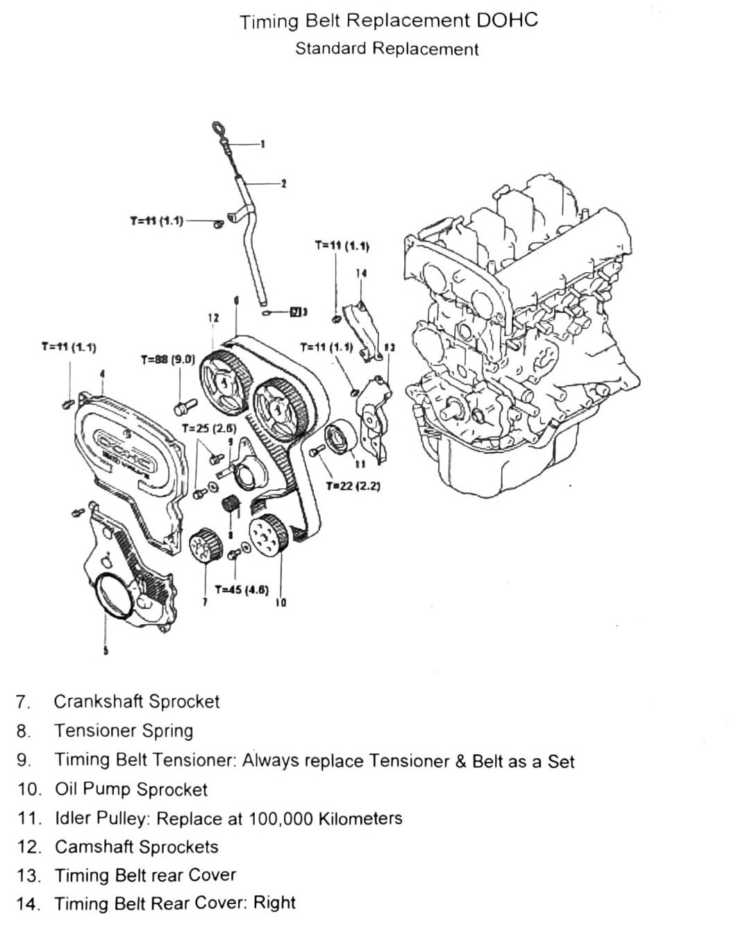
If further disassembly is required, continue removing:
- Crankshaft sprocket
- Tensioner spring
- Timing belt tensioner — always replace tensioner and belt as a set
- Oil pump sprocket
- Idler pulley — replace at 100,000km (62,137mi)
- Camshaft sprockets
- Timing belt rear cover
- Timing belt rear cover, right
Removal procedure
- Remove all accessory belts.
- Remove upper and lower timing belt covers.
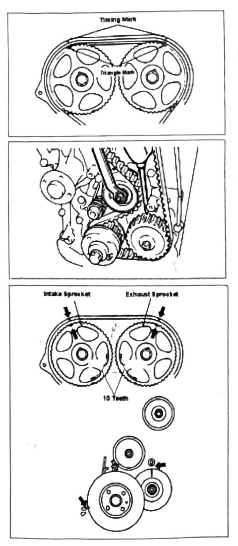
- Rotate the engine clockwise to the TDC position. Both intake and exhaust camshaft sprockets have triangle marks that line up with the timing marks as shown.
- Loosen the tensioner bolt.
- Remove the timing belt.
Note: if the vehicle has over 100,000km (62,137mi), replace the belt and tensioner as a set. Clean all parts before reassembly.
Installation procedure
- Use the alignment diagram to confirm sprocket and pulley alignment.
- The intake and exhaust sprockets will have their triangle marks pointed at the timing marks. Count ten (10) teeth from the center of the sprockets to the circular “O” marks, which indicate TDC.
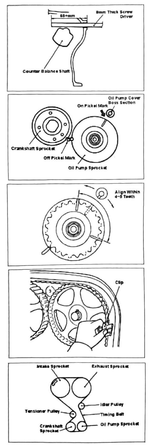
- Align the crankshaft pulley to the “TOP” mark.
- To prevent the oil pump from moving during alignment, slide an 8mm (0.315in)-thick flat-blade screwdriver through the side hole as shown — this holds the counterbalance shaft still. Minimum shaft/driver length: 65mm (2.559in).
- Align the dowel/pin alignment marks as shown in the diagram. (verify printed p.42) — source OCR renders this as “Pickel Marks”; likely a pin or dowel alignment mark, but confirm the exact term against the printed page.
- Using the close-up diagram of the oil pump sprocket, confirm the alignment marks fall within 4 to 5 gear teeth of each other.
- Install the timing belt. Use a large book-binding paper clip as shown to prevent movement during setup.
- Set the tensioner. Belt play between the intake and exhaust sprockets should be no more than 4 to 5mm (0.157–0.197in).
- Remove the paper clip. Rotate the engine one full rotation to verify TDC points still align.
- Assemble remaining components in reverse order.
Torque values
| Fastener | Torque |
|---|---|
| Crankshaft pulley/sprocket bolt | 88–98 N·m (9.0–10 kgf·m; 65–72 ft-lb) — matches Section 14/16 crank bolt spec |
| Timing belt tensioner nut | 25 N·m (2.6 kgf·m; 18 ft-lb) — matches Section 16 |
(verify printed p.39-40) — additional torque callouts visible in the source diagram could not be confidently matched to specific fasteners: T=11 N·m (1.1 kgf·m; 97 in-lb) (appears 4 times, likely timing belt cover bolts, as in Section 16), T=22 N·m (2.2 kgf·m; 16 ft-lb) (appears once — possibly the idler pulley bolt, since the idler pulley is the one component in this DOHC list not present in the SOHC list, but this attribution is not confirmed), and T=45 N·m (4.6 kgf·m; 33 ft-lb) (appears once, unidentified — note this is close to but not identical to the 4.5 kgf·m value on the SOHC page, confirm both against the printed pages).