Timing Belt Replacement (SOHC)
Note: Remove V-belts and pulleys before starting the steps below.
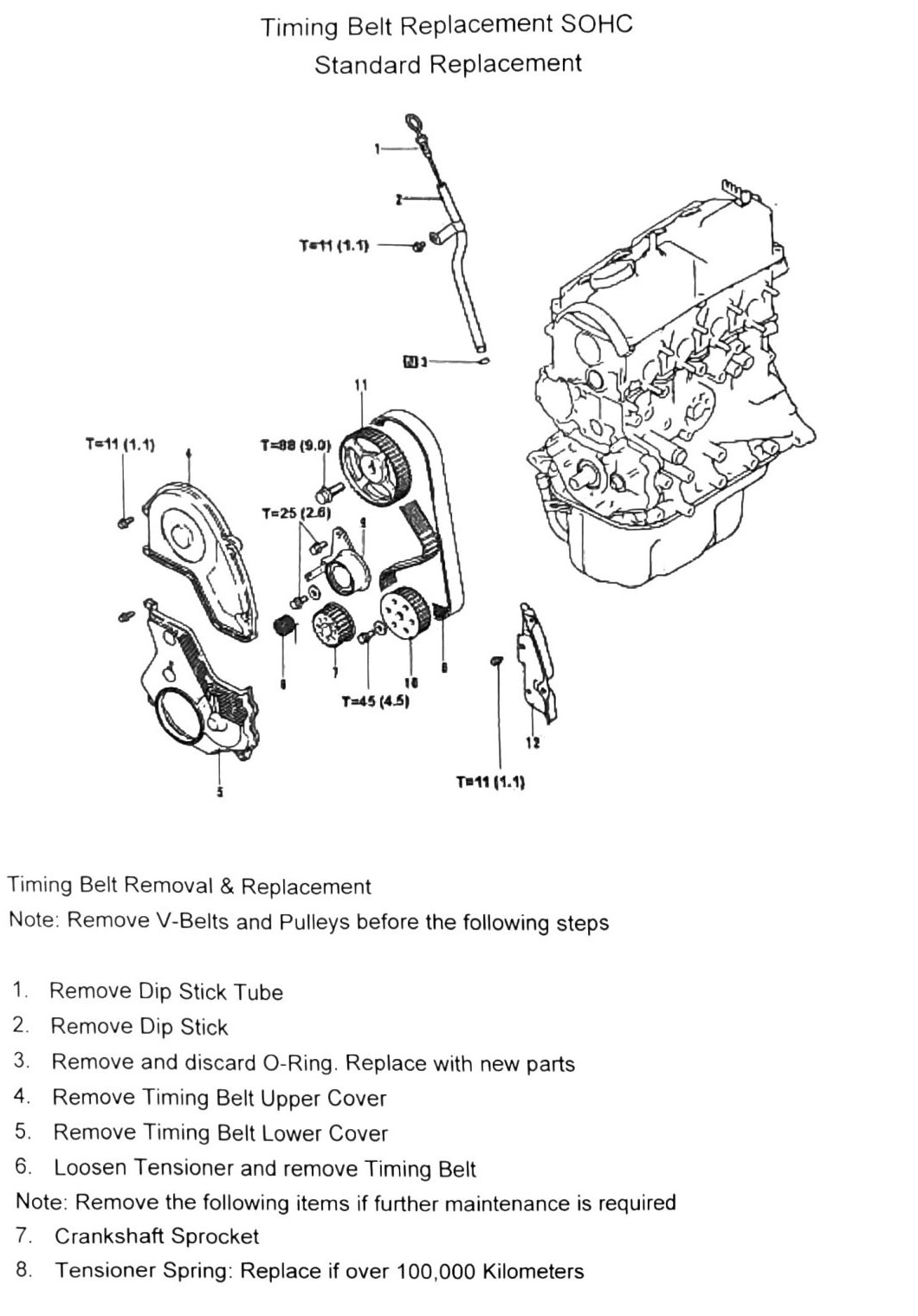
Component removal order
- Dip stick tube
- Dip stick
- O-ring (remove and discard — replace with new part)
- Timing belt upper cover
- Timing belt lower cover
- Loosen tensioner and remove timing belt
If further maintenance is required, continue removing:
- Crankshaft sprocket
- Tensioner spring — replace if over 100,000km (62,137mi)
- Tensioner unit — replace if over 100,000km (62,137mi)
- Oil pump sprocket
- Camshaft sprocket
- Timing belt rear cover
Note: the timing belt and tensioner assembly must be replaced as a set at 100,000km (62,137mi).
Timing belt removal
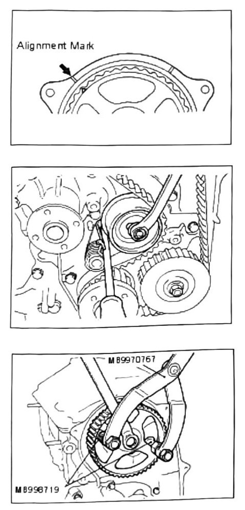
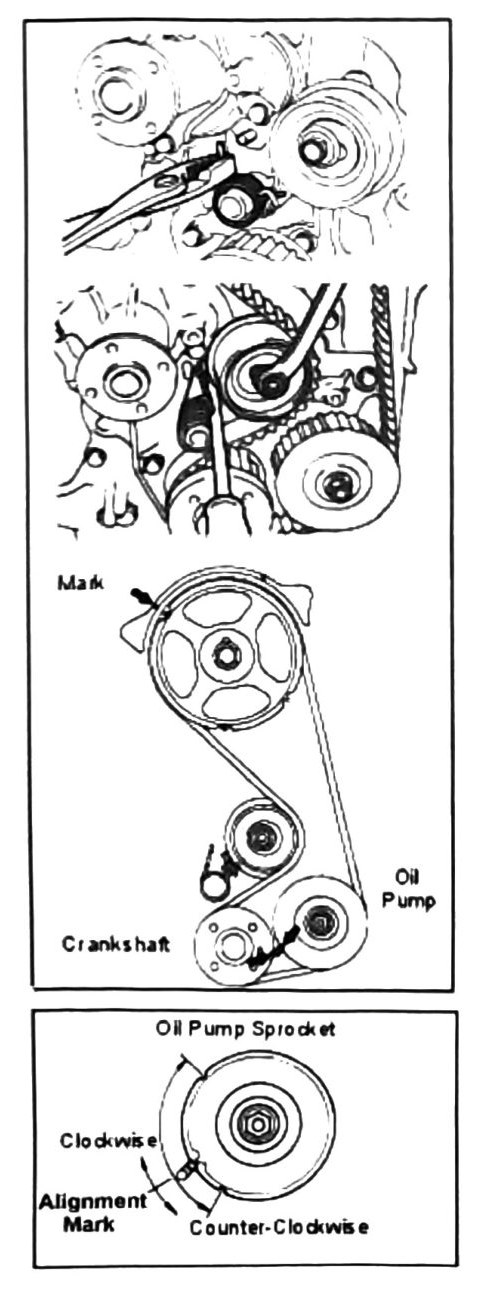
- Turn the engine clockwise until the camshaft sprocket triangle mark aligns with the reference mark shown. This is the No. 1 cylinder TDC point.
- Loosen the timing belt tensioner nut.
- Use a flat-blade screwdriver to loosen the tensioner spring as shown. Be careful not to damage the water pump case.
- Remove the timing belt.
- Inspect the camshaft sprocket; remove and replace if defects are detected, using camshaft holder tools MB990767 and MD998719.
Note: replace the water pump along with the timing belt if the water pump has over 60,000km (37,282mi) on it.
Oil pump sprocket / counterbalance shaft removal
Note: if the oil pump sprocket is removed, the counterbalance shaft must be held in position.
- Remove the oil plug on the side of the block.
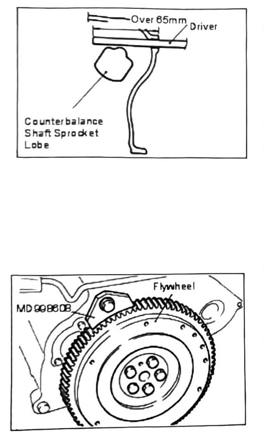
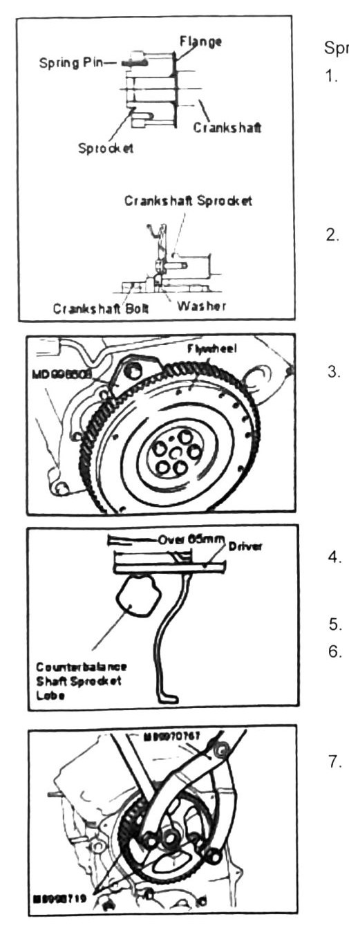
- Slide an 8mm (0.315in)-thick, rounded flat-blade driver (minimum 65mm (2.559in) length) through the orifice to hold the counterbalance shaft.
- Remove the oil pump “F” nut.
- Remove the sprocket.
Crankshaft bolt removal
- Install the flywheel retaining tool (MD998608) as shown.
- Remove the crankshaft bolt.
Installation
- Install the spring pin as shown.
- Install the crankshaft sprocket and washer.
- Attach the flywheel retainer and install the crankshaft bolt.
- Slide the 8mm (0.315in) driver through the orifice again to hold the counterbalance shaft (same as removal, min. 65mm (2.559in) length).
- Install the oil pump sprocket.
- Install the oil pump “F” nut.
- Attach the camshaft sprocket, using tools MD998719 and MB990767.
- Use a pair of pliers to install the tensioner spring. Take care not to damage the water pump during installation.
- Use a screwdriver to move the tensioner and tighten the nut. Do not fully tighten the belt until proper positioning is confirmed.
- Check all alignment marks.
- Use the oil pump sprocket alignment diagram (clockwise/counter-clockwise reference marks) to confirm correct sprocket orientation.
Torque values
| Fastener | Torque |
|---|---|
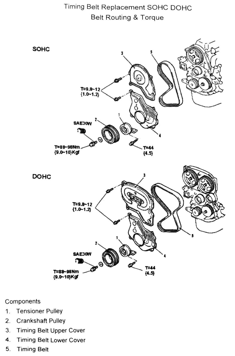
| Crankshaft pulley/sprocket bolt | 88–98 N·m (9.0–10 kgf·m; 65–72 ft-lb) |
| Timing belt tensioner nut | 25 N·m (2.6 kgf·m; 18 ft-lb) |
(verify printed p.32-38) — the source diagrams on these pages show several additional torque callouts that could not be confidently matched to a specific fastener after OCR: T=11 N·m (1.1 kgf·m; 97 in-lb) (appears 4 times, likely various timing belt cover bolts) and T=45 N��m (4.5 kgf·m; 33 ft-lb) (appears once, unidentified). Confirm against the printed diagram before use.
Note: coat all moving parts with SAE 30W engine oil before assembly. Never reuse oil seals.