Timing & Idle Speed Inspection
Note: Before checking timing, confirm all other related components are in proper working order.
- Inspect spark plugs and confirm proper gap.
- Inspect ignition coil(s) and wires for defects. Replace as necessary.
Tools required
- Timing light
- MUT-II diagnostic tester
- Paperclip
- Jump wire
Procedure
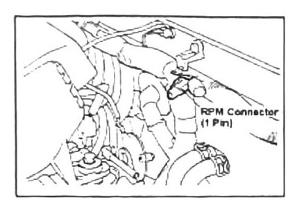
- Install a paperclip into the RPM test point connector (1-pin connector) as shown.
- Attach the MUT-II diagnostic tester, run the vehicle, and verify idle speed. Adjust idle speed if necessary before adjusting timing. Shut off the engine.
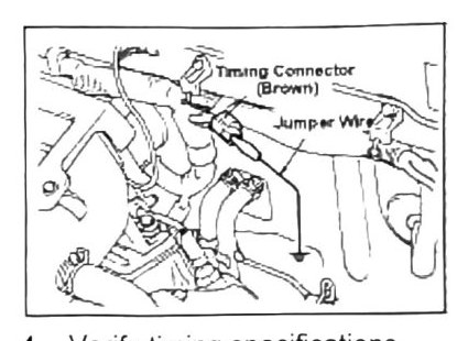
- Disconnect the MUT-II tester and connect a timing light. Run the engine.
- Verify timing against specifications below.
- If adjustment is required, loosen the crank sensor (distributor), located at the back of the engine attached to the camshaft, and adjust settings as required.
Timing / idle specifications
(verify printed p.27) — this table is badly scrambled by OCR in the source (rows and columns misaligned), and the same scrambled layout repeats identically on printed p.22 (see Section 8). The candidate values below could not be confidently mapped to a specific engine/transmission combination — treat as a checklist of values to confirm against the printed page, not a resolved table.
- Ignition timing candidates: BTDC 5°±2°, and BTDC 10°±2°
- Idle RPM candidates: 800±50 RPM, and 850±50 RPM
- CO% candidates: 1.0±0.5%, and “below 0.6%”
- HC ppm candidates: “below 300 ppm” (appears twice — possibly once per engine)
- Fast idle candidates: 1500±50 RPM (A/C on), 1300±50 RPM (non-A/C)
The labels loosely associated with these values in the source include “SOHC M/T,” “SOHC A/T,” “SOHC 2 Valve,” and “SOHC/DOHC 5 Valve Turbo,” but none of these pairings survived OCR with confidence.