Engine Settings & Adjustment Specifications
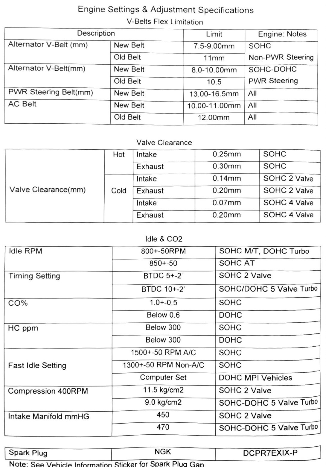
This section collects the baseline adjustment specifications for the 4A30 engine family (belt deflection, valve clearance, timing, idle, compression, and vacuum limits) and the valve clearance adjustment procedure itself. SOHC (XR grade, 16-valve, naturally aspirated) and DOHC Turbo (VR grade, 20-valve, intercooled turbo — our truck) specs differ and are labeled separately throughout.
(verified against scan p.22, p.25-26, 2026-08-30) — page layout confirmed: printed p.22 is the summary spec table (“Engine Settings & Adjustment Specifications”), p.25 is “Valve Clearance SOHC” (procedure + measurement chart), and p.26 is “Lash Adjusters DOHC” (notes + measurement chart). Content is grouped here by topic under Section 8’s title rather than by page sequence.
V-belt deflection limits
| Belt | New belt limit | Old (worn) belt limit | Engine | Notes |
|---|---|---|---|---|
| Alternator V-belt | 7.5–9.00mm (0.295–0.354in) | 11mm (0.433in) | SOHC | Non-power-steering vehicles |
| Alternator V-belt | 8.0–10.00mm (0.315–0.394in) | 10.5mm (0.413in) | SOHC-DOHC | Power-steering equipped |
| Power steering belt | 13.00–16.5mm (0.512–0.650in) | — | All | — |
| A/C belt | 10.00–11.00mm (0.394–0.433in) | 12.00mm (0.472in) | All | — |
Belt tension gauge reading should indicate 25 to 35kgf (55–77 lbf). See Section 10 for the full inspection and routing procedure.
Valve clearance specifications
Measured cold (ambient temperature) and hot, per the measurement charts on printed p.25 (SOHC) and p.26 (DOHC):
| Engine | Valve | Hot clearance | Cold clearance |
|---|---|---|---|
| SOHC | Intake | 0.25mm (0.010in) | 0.14mm (0.006in) |
| SOHC | Exhaust | 0.30mm (0.012in) | 0.20mm (0.008in) |
| DOHC Turbo (5-valve) | Intake | 0.20mm (0.008in) | 0.07mm (0.003in) |
| DOHC Turbo (5-valve) | Exhaust | 0.30mm (0.012in) | 0.17mm (0.007in) |
Valve adjustment nut torque (SOHC): 9±1 N·m (80±9 in-lb).
Note: DOHC Turbo engines use hydraulic lash adjusters (lifters) that are self-adjusting and non-serviceable — there is no manual clearance adjustment on DOHC. The cold/hot DOHC figures above are inspection/wear-limit reference values, not an adjustment target.
(verified against scan p.22, p.25-26, 2026-08-30) — the “SOHC 2 Valve” / “SOHC 4 Valve” labels are genuinely printed that way on p.22, not OCR damage (the manual’s translation is loose with valve counts; the p.26 chart calls the DOHC engine “DOHC Turbo 5 Valve Engine”). The p.25 SOHC chart (hot 0.25/0.30, cold 0.14/0.20) and p.26 DOHC chart (hot 0.20/0.30, cold 0.07/0.17) match the table above exactly. One genuine printed discrepancy: the p.22 summary lists the “SOHC 4 Valve” (= DOHC) cold exhaust clearance as 0.20mm, while the p.26 DOHC measurement chart says 0.17mm. The table above keeps the p.26 chart value; on DOHC this is a reference value only (hydraulic lifters).
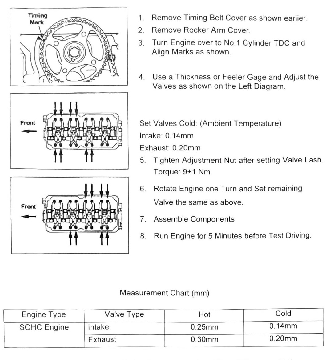
SOHC valve clearance adjustment procedure
- Remove timing belt cover (see Section 16) and rocker arm cover.
- Turn engine to No. 1 cylinder TDC and align timing marks.
- Use a feeler gauge to check/adjust valves cold: Intake 0.14mm (0.006in), Exhaust 0.20mm (0.008in).
- Tighten adjustment nut after setting valve lash. Torque: 9±1 N·m (80±9 in-lb).
- Rotate engine one full turn and set the remaining valves the same way.
- Reassemble components.
- Run the engine for 5 minutes before test-driving.
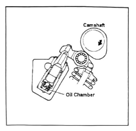
DOHC hydraulic lifter notes
- DOHC hydraulic tappets cannot be repaired — replace as a set if clearance fails.
- Common failure causes: dirty engine oil clogging the oil chamber, or overheating baking oil deposits into the chamber.
- Failing lifters are usually first noticeable as a “clacking” sound.
- After an oil change on DOHC engines, run the engine 30 seconds at 3000rpm before allowing it to idle, to clear the oil chamber of old oil.
Timing and idle specifications
(verified against scan p.22 and p.27, 2026-08-30) — both printed tables are legible in the page scans and agree with each other. Confirmed mapping:
| Item | Value | Applies to |
|---|---|---|
| Ignition timing | BTDC 5°±2° | SOHC (“SOHC 2 Valve”) |
| Ignition timing | BTDC 10°±2° | DOHC Turbo (“SOHC/DOHC 5 Valve Turbo”) |
| Idle RPM | 800±50 RPM | SOHC M/T and DOHC Turbo |
| Idle RPM | 850±50 RPM | SOHC A/T |
| CO% | 1.0±0.5% | SOHC |
| CO% | Below 0.6% | DOHC |
| HC ppm | Below 300 | SOHC |
| HC ppm | Below 300 | DOHC |
| Fast idle | 1500±50 RPM (A/C) | SOHC |
| Fast idle | 1300±50 RPM (non-A/C) | SOHC |
| Fast idle | Computer set (not adjustable) | DOHC MPI vehicles |
Note: the p.27 table prints the “Timing Setting” row pair twice (above and below the Idle RPM rows) with identical values — a layout quirk of the printed page, not extra data. Full procedure: Section 11.
Compression specification
| Engine | Compression @ 400 RPM cranking |
|---|---|
| SOHC | 11.5 kg/cm² (164 psi) |
| DOHC Turbo | 9.0 kg/cm² (128 psi) |
(verified against scan p.22 and p.28, 2026-08-30) — both printed pages read cleanly: 11.5 kg/cm² is labeled “SOHC 2 Valve” (= the SOHC/XR engine) and 9.0 kg/cm² is labeled “SOHC-DOHC 5 Valve Turbo” (= the DOHC turbo/VR engine), identically on both pages. The odd label wording is genuinely printed, not OCR damage. Full procedure: Section 12.
Intake manifold vacuum
(verified against scan p.22 and p.29, 2026-08-30) — both printed pages read cleanly and genuinely differ; this is a real discrepancy in the book, not an OCR artifact. Printed p.22’s summary row “Intake Manifold mmHG” lists 450 (17.72 inHg, SOHC 2 Valve) and 470 (18.51 inHg, SOHC-DOHC 5 Valve Turbo); printed p.29’s procedure states only “Vacuum Limit: 400mmHg@idle (15.75 inHg)” with no engine split. The two pages may be describing different quantities (per-engine expected readings vs. a single minimum limit), but the manual does not say so — treat 400mmHg@idle as the procedure’s pass/fail limit and 450/470 as the p.22 summary figures.
Spark plug
- NGK DCPR7EXIX-P
- Note: see the vehicle information sticker for the correct spark plug gap — no gap value is given in this section of the manual.