Front Suspension Components
Note: see previous sections for related component removal details (strut assembly, alignment).
Torque specifications
The diagram on this page shows seven distinct torque callouts. The OCR text does not label which fastener in the procedure below each value applies to — listed here as read, (verify printed p.259) before use:
| Torque value |
|---|
| 53 N·m (5.3 kgf·m; 39 ft-lb) |
| 43 N·m (4.3 kgf·m; 32 ft-lb) |
| 20 N·m (2.0 kgf·m; 15 ft-lb) |
| 59-71 N·m (6.0-7.2 kgf·m; 44-52 ft-lb) |
| 105 N·m (10.5 kgf·m; 77 ft-lb) |
| 54-69 N·m (5.5-7.0 kgf·m; 40-51 ft-lb) |
| 59 N·m (6.0 kgf·m; 44 ft-lb) |
Lower Arm Component Removal
- Remove strut bar bracket attachment bolts.
- Strut bar attachment bolts (2).
- Clamp.
- Disconnect stabilizer link.
- Remove ball joint nut.
- Press out ball joint and lower assembly.
- Snap ring.
- Dust cover.
- Remove bushing: remove lower arm.
- Washer.
- Strut bar bushing “A”.
- Strut bar bracket.
- Strut bar bushing “B”.
- Remove strut bar.
Note: bushings must be replaced once removed. See Parts Catalogue.
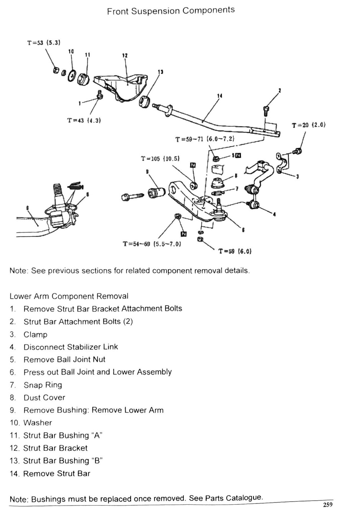
OCR note: the 14-step procedure list above was printed sequentially and required no reordering. The seven torque values, however, are not individually labeled against specific fasteners in the OCR text — (verify printed p.259) to match each torque to its bolt before use.