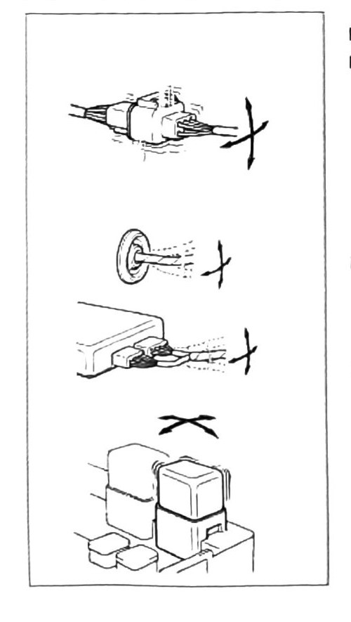
Wiring Harness Connection Inspection & Removal
Loose, corroded, or broken harness connectors can cause the computer unit to fail or run improperly. Improper connector removal technique can damage both the connector pins and the connector body itself, so follow the steps below rather than pulling on the harness directly.
Connector removal
- Press the locking tab downward.
- Remove the connector with a left-right rocking motion, pulling back until it releases.
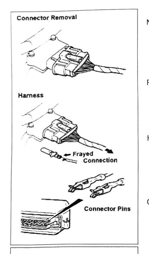
Inspecting the harness
- Harness wires — lightly pull back on the wire harness to check for broken or frayed connections.
- Connector pins & clips — inspect for damaged pins and clips, and for corrosion. Clean or replace as required.
- Individual wires — lightly pull back on individual wires to check for proper connection. Repair or replace as necessary.
- Female connectors — use Test Lead MB991219 (or equivalent) to check connectivity. Clean or replace as required.
Note: use only approved electrical component cleaner on electrical connectors. Never use carburetor cleaner or other industrial chemicals on plastic connectors — this can cause component failure.
Fusible links
The Pajero Mini has fusible links installed in all main circuits to protect against damage from power surges or short circuits.
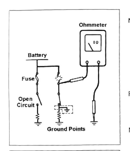
- Test fusible links and their circuits with an ohmmeter.
- See the Pajero Mini Electrical Guide Book for full circuit diagrams.
Fusible link test procedure: use an ohmmeter to check circuit integrity on any fusible link suspected of having failed.
Note: disconnect the negative (-) battery cable before replacing electrical components.
Connector and relay connections
- Verify proper connector connections and relay seating against the manual’s diagrams.
- Check firewall grommets for flexibility; replace any that are cracked or torn.
- Verify computer and control box connections as shown in the diagrams.
- Install and remove relay units as shown in the diagrams.