Free Wheel Locking System Overhaul (4WD)
Components
- Pin
- Vacuum Hose
- Free Wheel Engage Switch Assembly
- Differential Mount Left Bracket
- Free Wheel Housing
- Collar
Fastener torques
| Torque | Nm (kgf·m) |
|---|---|
| T = 35 | (3.6; 26 ft-lb) |
| T = 49 | (5.0; 36 ft-lb) |
| T = 49–59 | (5.0–6.0; 36–44 ft-lb) |
| T = 83 | (8.5; 61 ft-lb) |
| T = 59–69 | (6.0–7.0; 44–51 ft-lb) |
A 2-3 mm (0.079–0.118 in) clearance/gap is also called out on the diagram (component not specified in OCR — verify printed p.223).
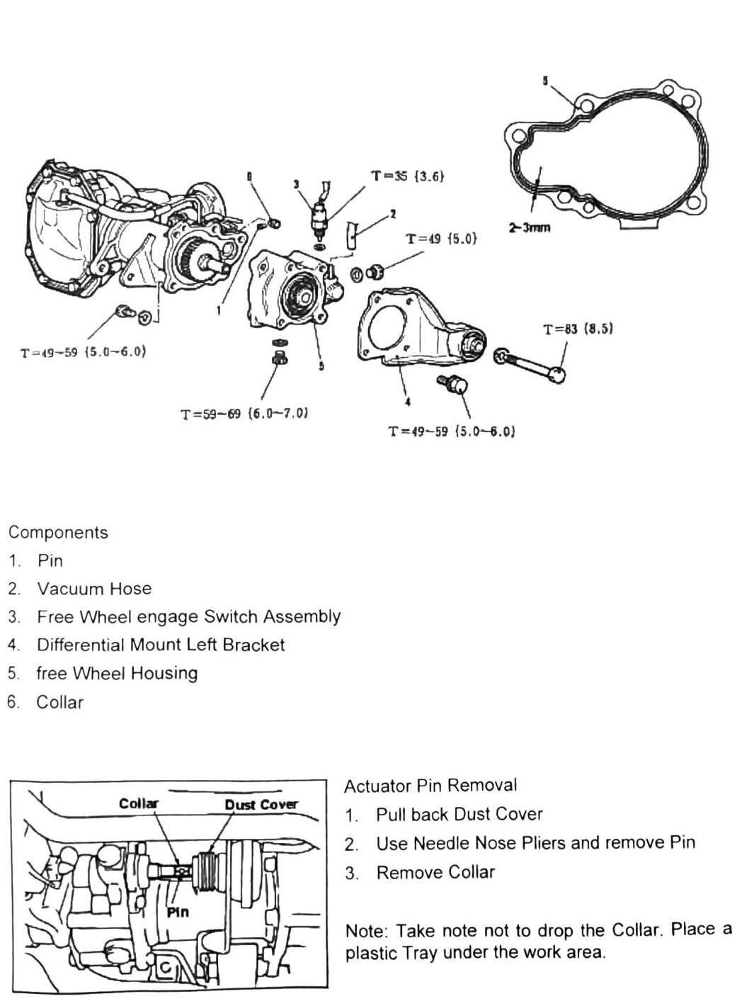
Actuator pin removal
- Pull back dust cover.
- Use needle-nose pliers and remove pin.
- Remove collar.
Note: take care not to drop the collar — place a plastic tray under the work area.
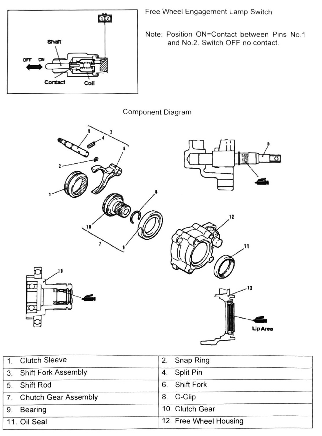
Free wheel engagement lamp switch
Switch contact logic: ON = contact between pins No. 1 and No. 2. OFF = no contact.
Component diagram
- Clutch Sleeve
- Snap Ring
- Shift Fork Assembly
- Split Pin
- Shift Rod
- Shift Fork
- Clutch Gear Assembly
- C-Clip
- Bearing
- Clutch Gear
- Oil Seal
- Free Wheel Housing
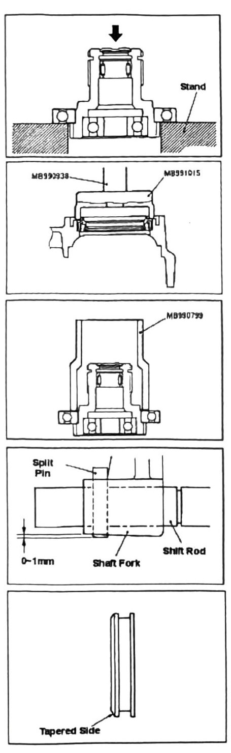
Bearing removal
- Place the unit on a press stand and press out bearing as shown (tool MB991015).
- Install new oil seal (tool printed as “MB992938”/“MB190799” — (verify printed p.225 — illegible, likely MB990799 given step 3 below)).
- Use bearing installer MB990799 and install new bearing.
Split pin installation
- Use the guide shown for installing a new split pin. Gap/clearance called out as 0-1 mm (0–0.039 in).
Note: never reuse split pins.
Clutch sleeve installation
- Install the clutch sleeve with the tapered end facing the driveshaft and the flat side facing the differential gear.