MPI Fuel System & Component Chart — DOHC
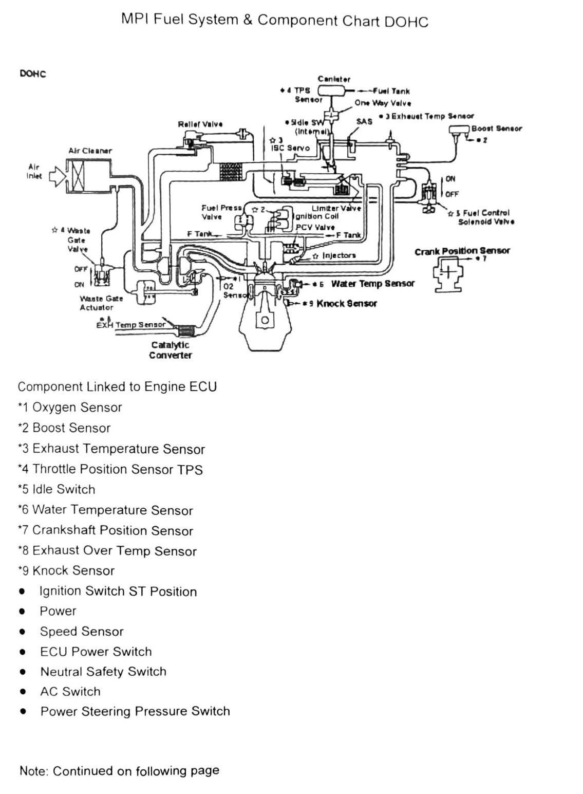
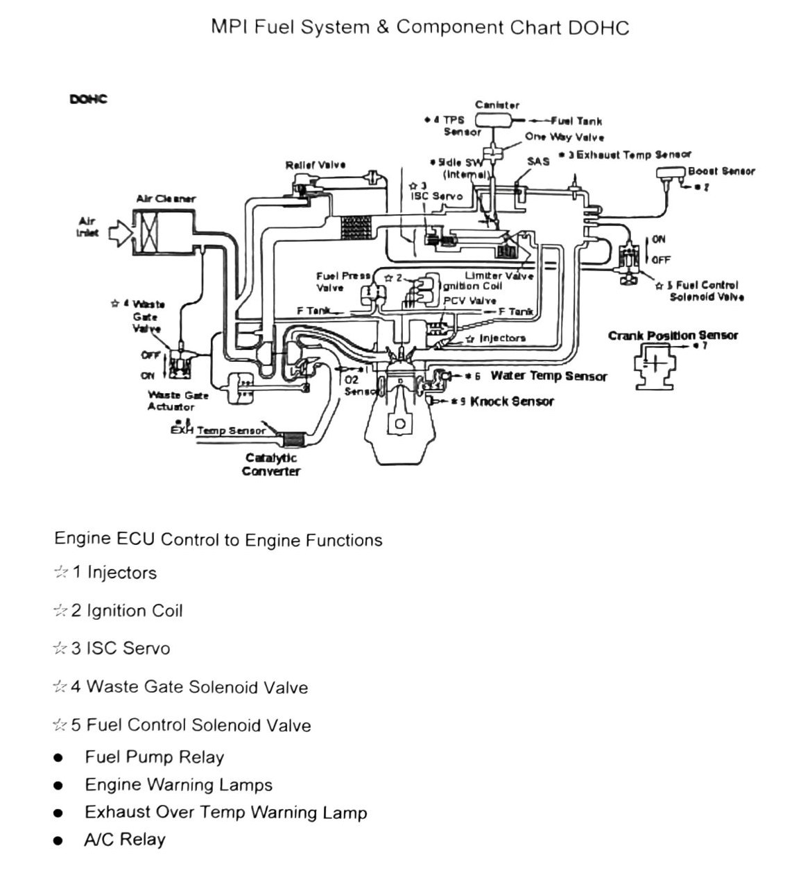
Component/system schematic for the intercooled-turbo DOHC MPI fuel system (VR grade — our truck’s 4A30 DOHC turbo). Two source diagrams (printed p.119-120) repeat the same sensor/ECU/turbo-control loop; the p.120 copy adds the ECU control-output list. OCR could not recover diagram line-routing — only labeled components are transcribed below.
Components linked to Engine ECU (inputs)
- Oxygen Sensor (*1)
- Boost Sensor (*2)
- Exhaust Temperature Sensor (*3)
- Throttle Position Sensor, TPS (*4)
- Idle Switch (*5)
- Water Temperature Sensor (*6)
- Crankshaft Position Sensor (*7)
- Exhaust Over Temp Sensor (*8)
- Knock Sensor (*9)
- Ignition Switch ST position
- ECU Power Switch
- Neutral Safety Switch
- A/C Switch
- Power Steering Pressure Switch
- Speed Sensor
Footnote markers *1-*9 above were reconstructed from two overlapping OCR passes over the same diagram footnote block (printed p.119) — one fragment gave *1, *2, *5 plus unlabeled “Water Temp Sensor” and “Knock Sensor,” the other gave *3, *4, *6, *7, *8, *9. The two fragments do not conflict and combine into a complete, non-contradictory *1-*9 sequence. (verify printed p.119) against a clean scan before treating as fully authoritative.
Other diagram components (fuel/vacuum/turbo circuit)
- Fuel Tank, One-Way Check Valve, Relief Valve, Canister
- Idle SW (Internal), SAS, ISC Servo, Air Cleaner, Air Inlet
- Fuel Pressure Valve, Fuel Tank Limiter Valve
- Waste Gate Valve, Waste Gate Actuator (ON/OFF states shown in diagram)
- Fuel Control Solenoid Valve (ON/OFF states shown in diagram)
- Ignition Coil, PCV Valve
- Injectors, Catalytic Converter, EXH Temp Sensor
- A/C Relay
ECU control outputs (printed p.120 chart)
- Injectors
- Ignition Coil
- ISC Servo
- Waste Gate Solenoid Valve
- Fuel Control Solenoid Valve
Additional outputs (unordered in source): Fuel Pump Relay, Engine Warning Lamps, Exhaust Over Temp Warning Lamp.
(verify printed p.120) — “6 Water Temp Sensor” and “9 Knock Sensor” also appear inline with this output list in the OCR, which conflicts with their classification as ECU inputs on p.119. Most likely this is OCR bleed-through from the shared diagram legend rather than a genuine second appearance as outputs — flag before publishing; do not treat Water Temp Sensor or Knock Sensor as ECU outputs without checking a clean scan.