Cylinder Head & Valve System — SOHC/DOHC
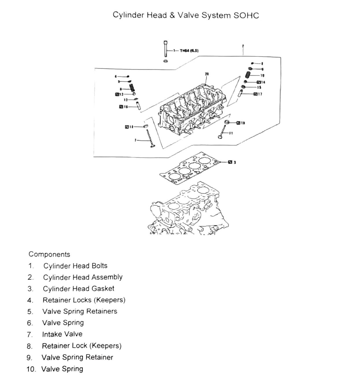
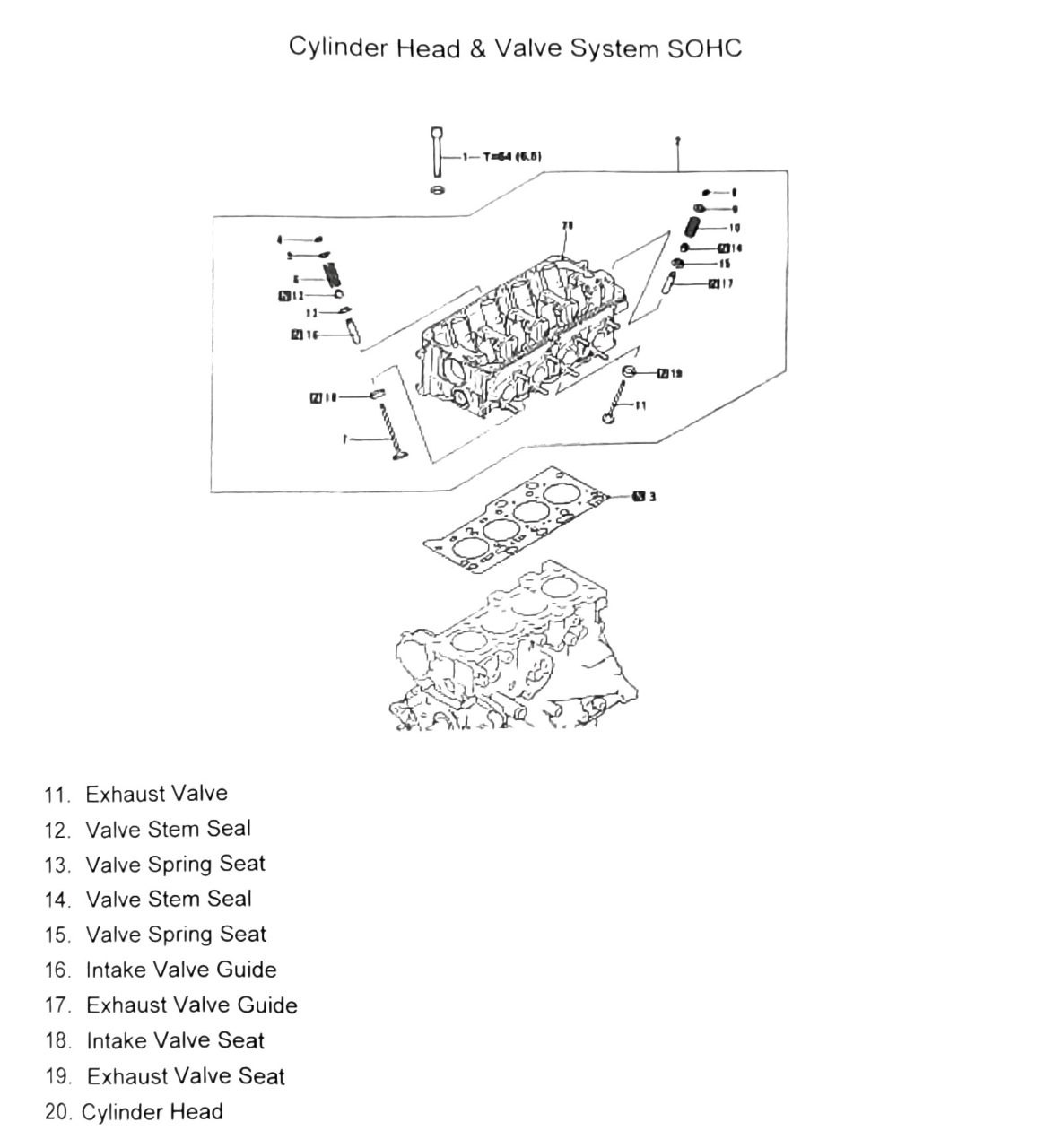
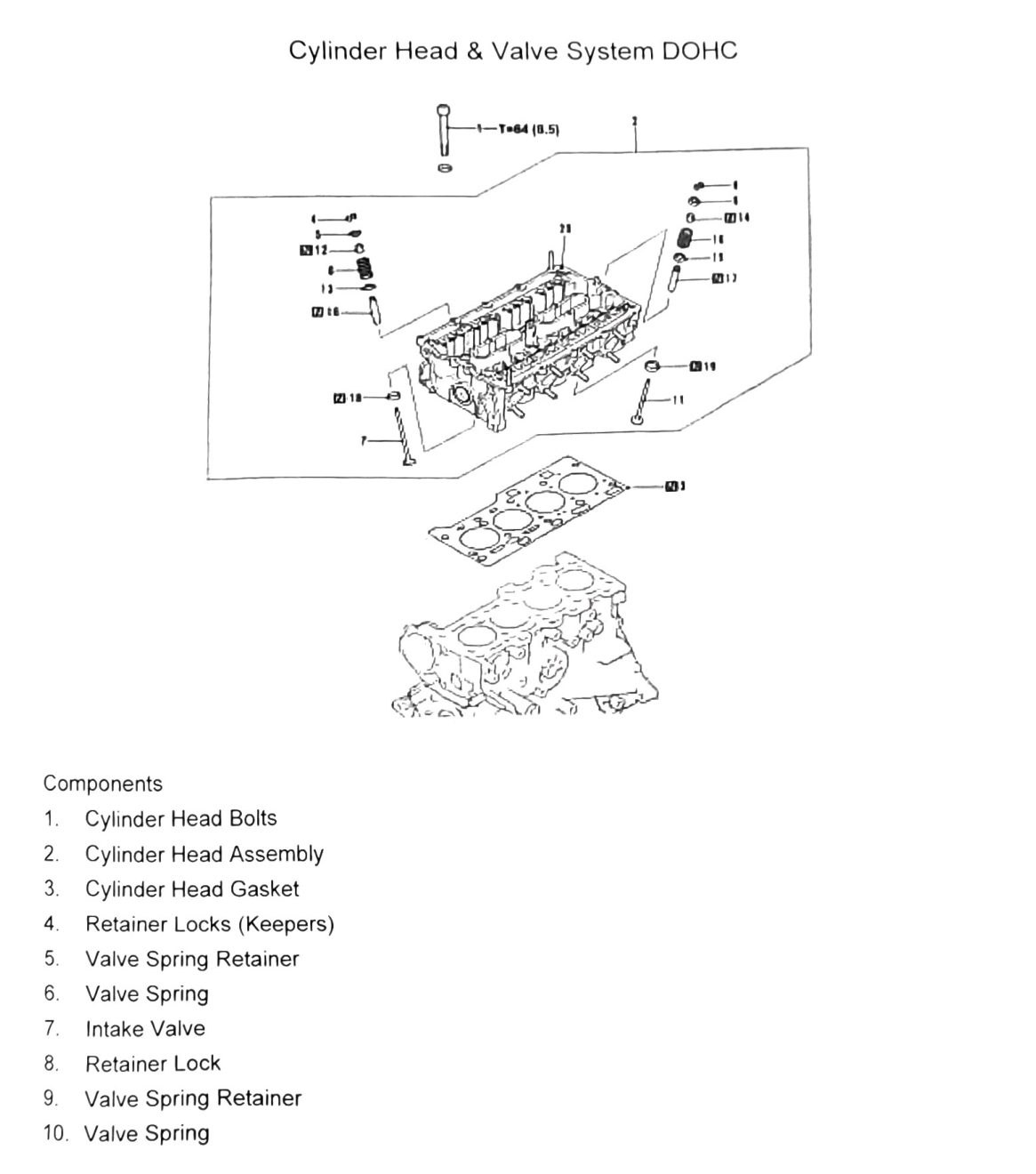
The component list is nearly identical between SOHC and DOHC (both use the same 20-item breakdown: bolts, head assembly, gasket, keepers, retainers, springs, valves, seals, guides, seats). Differences called out below are engine-specific; everything else applies to both.
Component removal order (SOHC)
- Cylinder head bolts
- Cylinder head assembly
- Cylinder head gasket
- Retainer locks (keepers)
- Valve spring retainers
- Valve spring
- Intake valve
- Retainer lock (keepers)
- Valve spring retainer
- Valve spring
- Exhaust valve
- Valve stem seal
- Valve spring seat
- Valve stem seal
- Valve spring seat
- Intake valve guide
- Exhaust valve guide
- Intake valve seat
- Exhaust valve seat
- Cylinder head
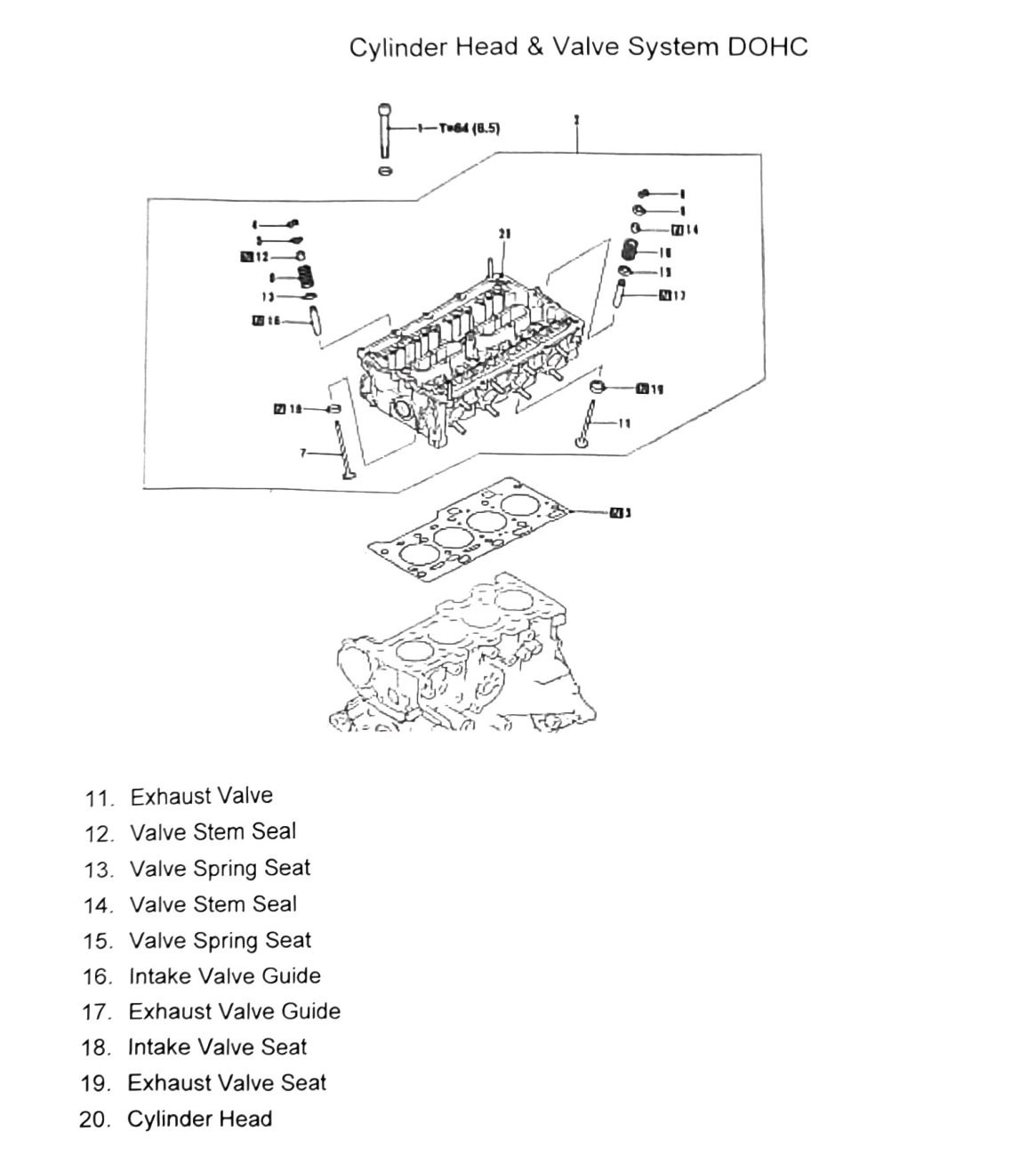
Component removal order (DOHC)
Same 20-item list as SOHC above (bolts, head, gasket, keepers, retainers, springs, intake/exhaust valves, seals, seats, guides, cylinder head).
Cylinder head bolt torque — SOHC vs DOHC
Both engines use the same cylinder head bolt torque:
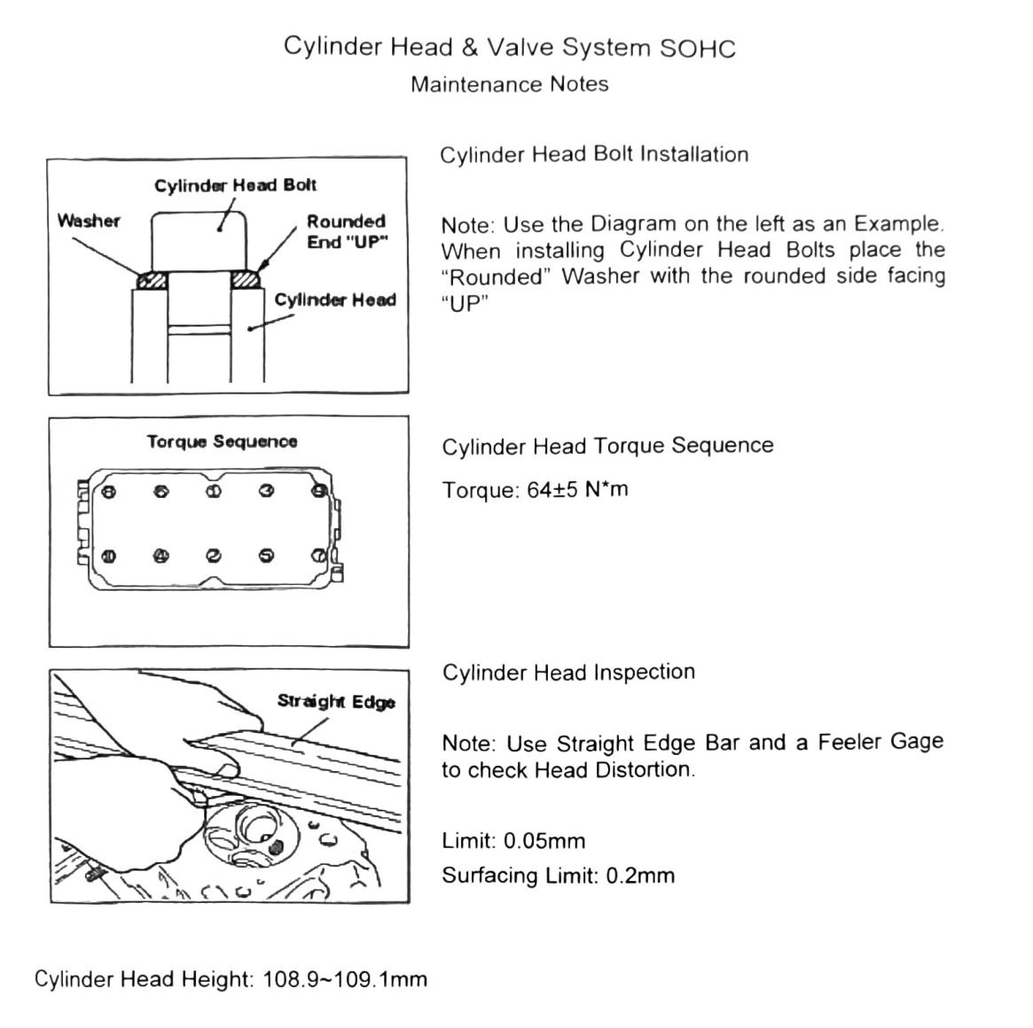
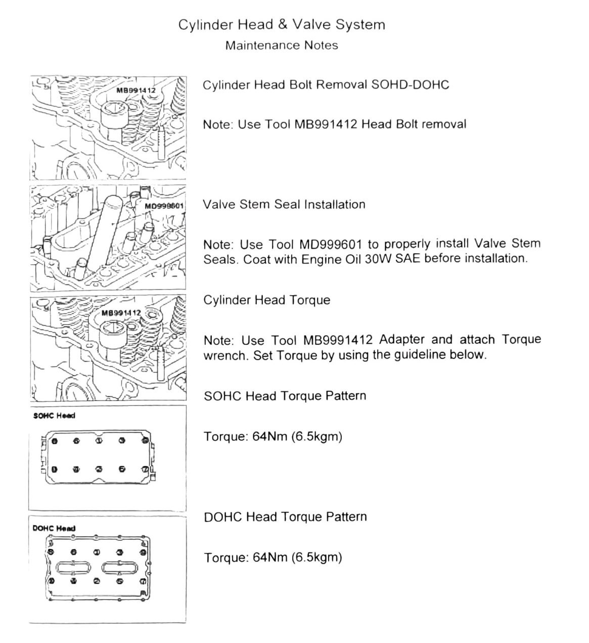
Torque: 64±5 N·m (6.5 kgf·m; 47±3.7 ft-lb)
This is confirmed by clean restatements for both SOHC (“Cylinder Head Torque Sequence… Torque: 64±5 N·m”) and DOHC (“DOHC Head Torque Pattern… Torque: 64Nm (6.5kgm)”).
(verify printed p.95-96) — the DOHC exploded-view diagram fragments read the kgf·m figure as “T-64 (8.5)” rather than “(6.5)”. Given two independent clean text restatements both say 6.5 kgf·m, this is most likely an OCR misread of the diagram (8 for 6), but flagging since the raw diagram text disagrees with the prose.
Cylinder head bolt installation
Note: When installing cylinder head bolts, place the rounded washer with the rounded side facing “UP.”
Use Tool MB991412 for head bolt removal, with a torque wrench adapter for installation, following the torque sequence diagram.
Cylinder head inspection
Use a straight-edge bar and feeler gauge to check head distortion.
| Item | Value |
|---|---|
| Distortion limit | 0.05mm (0.002in) |
| Surfacing limit | 0.2mm (0.008in) |
| Cylinder head height | 108.9-109.1mm (4.287–4.295in) (verify printed p.91) |
(verify printed p.91) — this cylinder head height figure conflicts with the Engine Specifications table (see 34-engine-specifications.md, printed p.78), which scans as “109-109.1mm.” The lower bound differs (108.9 vs 109). Confirm before machining a head.
Valve spring removal & replacement
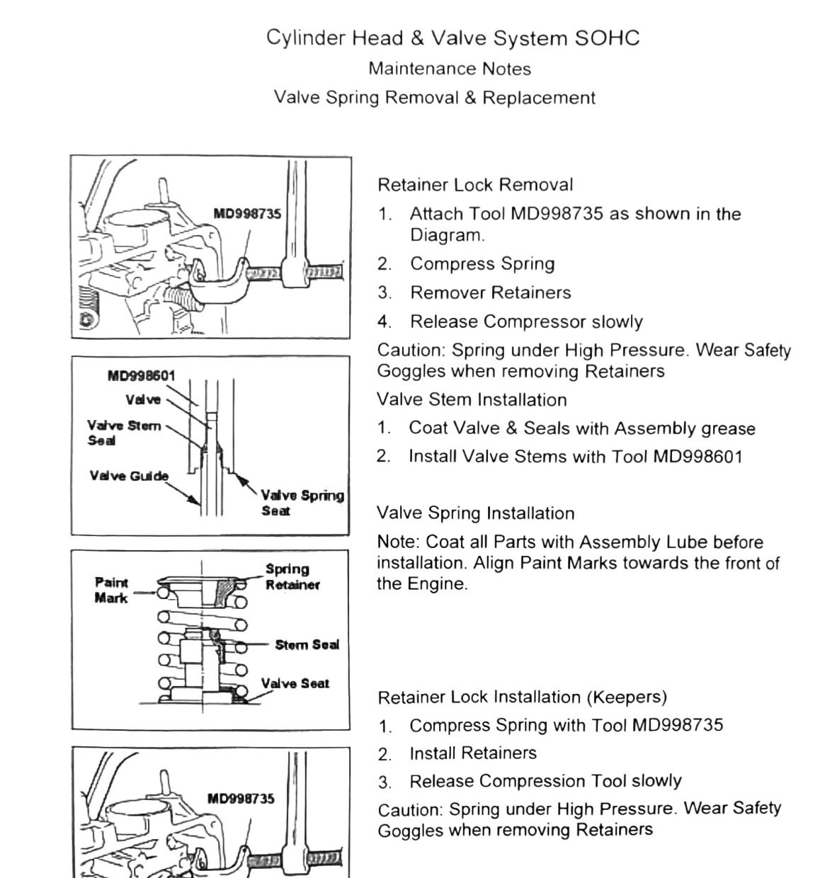
- Attach tool MD998735 as shown.
- Compress spring.
- Remove retainers.
- Release compressor slowly.
Caution: Spring under high pressure. Wear safety goggles when removing retainers.
Valve stem installation: coat valve & seals with assembly grease, install valve stems with tool MD998601.
Valve spring installation: coat all parts with assembly lube before installation; align paint marks toward the front of the engine.
Retainer lock (keeper) installation: compress spring with tool MD998735, install retainers, release compression tool slowly (same caution as removal).
Valve inspection
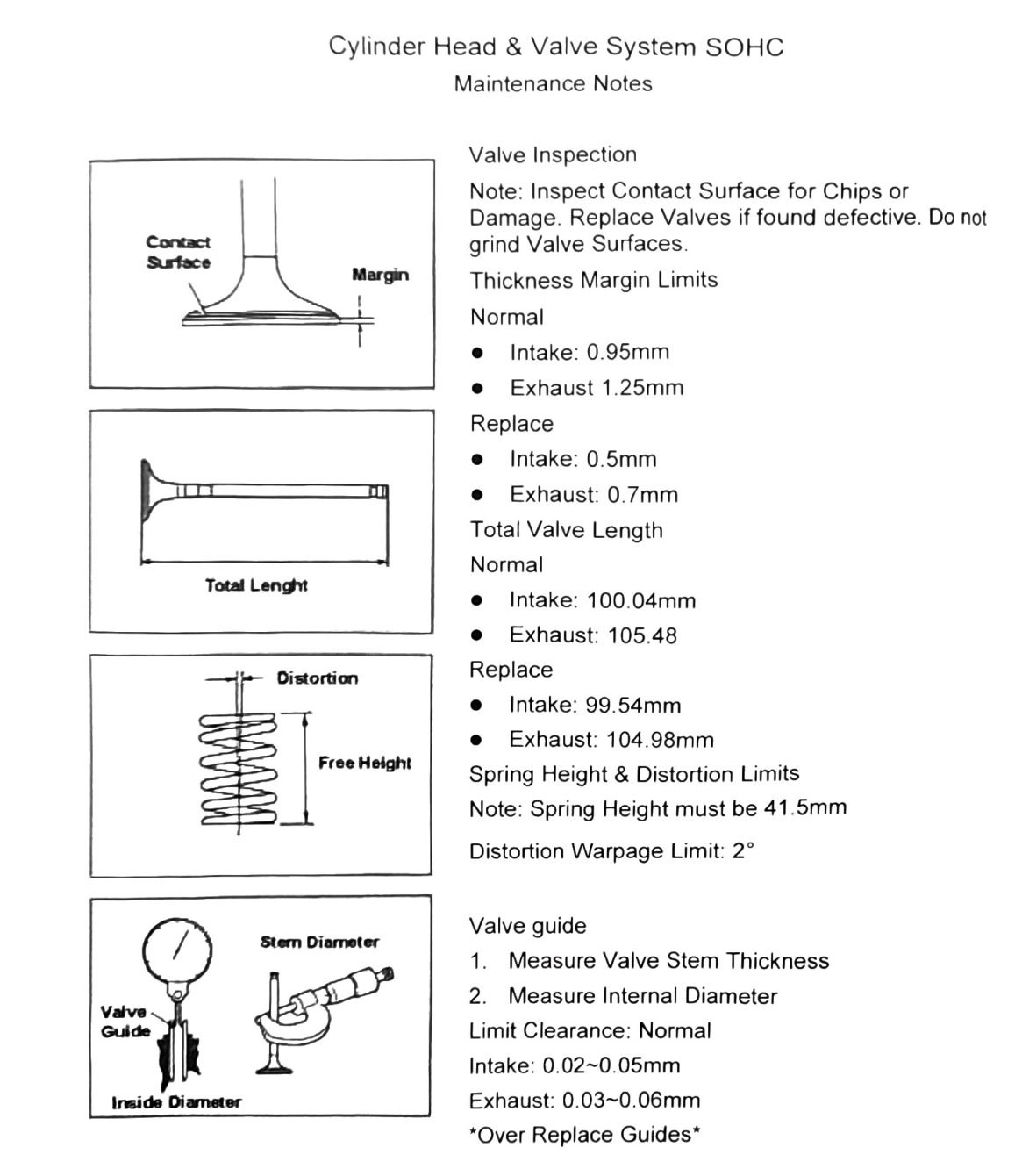
Note: Inspect contact surface for chips or damage. Replace valves if found defective. Do not grind valve surfaces.
| Item | Normal (Intake/Exhaust) | Replace (Intake/Exhaust) |
|---|---|---|
| Margin thickness | 0.95mm (0.037in) / 1.25mm (0.049in) | 0.5mm (0.020in) / 0.7mm (0.028in) |
| Total valve length | 100.04mm (3.939in) / 105.48mm (4.153in) | 99.54mm (3.919in) / 104.98mm (4.133in) |
Valve spring:
- Free height: must be 41.5mm (1.634in) — (verify printed p.92-93), see note below.
- Distortion/warpage limit: 2°
(verify printed p.92-93) — this maintenance-note restatement of valve spring free height (“41.5mm”) conflicts with the Engine Specifications table figure (“41.15mm” — see 34-engine-specifications.md). Confirm the correct value before setting up a spring; do not average or guess between them.
Valve guide-to-stem clearance (normal, inside diameter):
| Guide | Clearance |
|---|---|
| Intake | 0.02-0.05mm (0.001–0.002in) |
| Exhaust | 0.03-0.06mm (0.001–0.002in) |
Note: Over this clearance, replace guides.
Valve seat height (deck-to-tip) and oversize seats
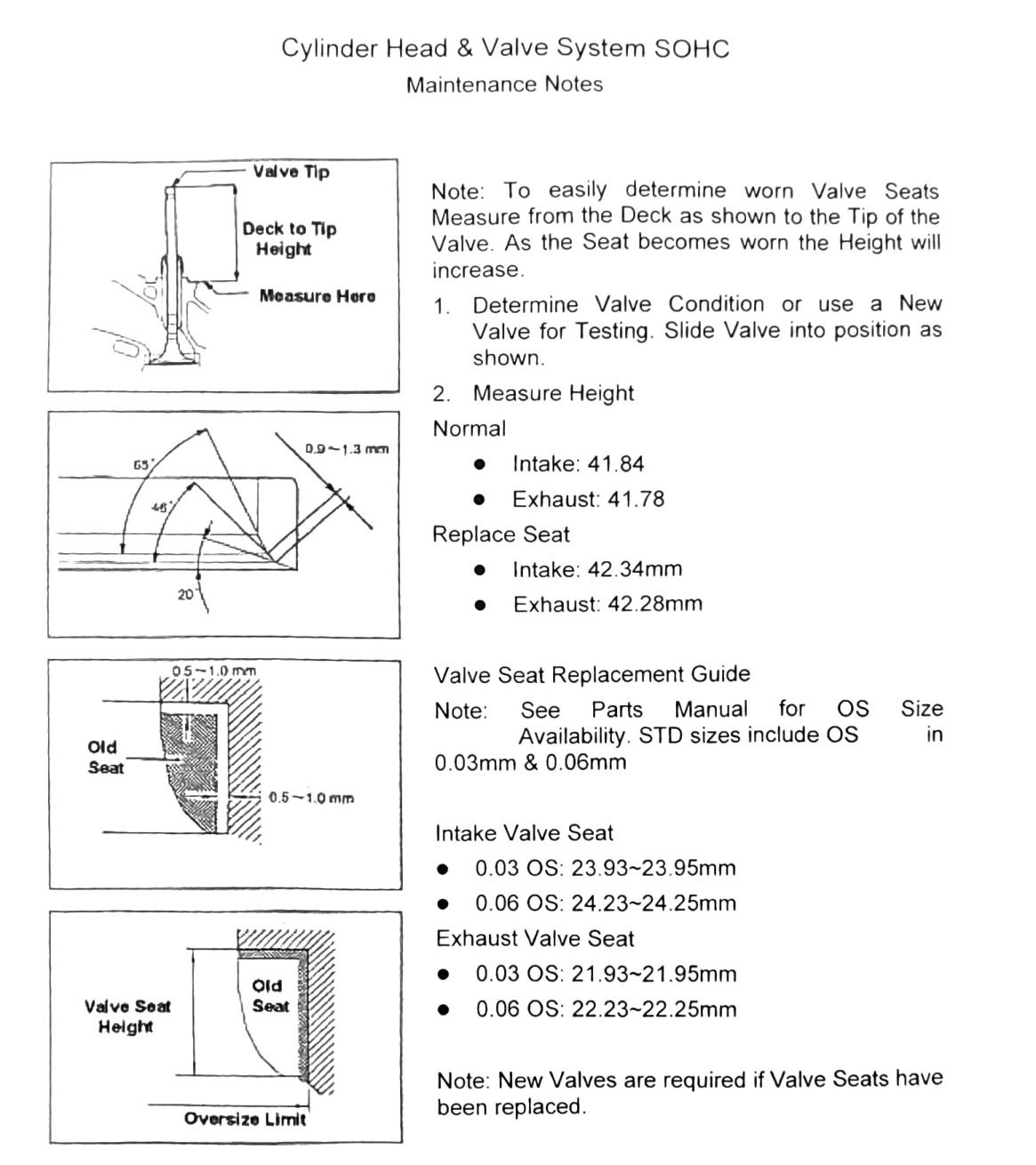
Note: To determine worn valve seats, measure from the deck to the tip of the valve. As the seat wears, this height increases.
| Item | Normal (Intake/Exhaust) | Replace-seat (Intake/Exhaust) |
|---|---|---|
| Deck-to-tip height | 41.84mm (1.647in) / 41.78mm (1.645in) | 42.34mm (1.667in) / 42.28mm (1.665in) |
Note: New valves are required if valve seats have been replaced.
Valve seat oversize availability (STD includes 0.03mm & 0.06mm OS):
| Oversize | Intake seat diameter | Exhaust seat diameter |
|---|---|---|
| 0.03 OS | 23.93-23.95mm (0.942–0.943in) | 21.93-21.95mm (0.863–0.864in) |
| 0.06 OS | 24.23-24.25mm (0.954–0.955in) | 22.23-22.25mm (0.875–0.876in) |
Valve guide protrusion and oversize diameter
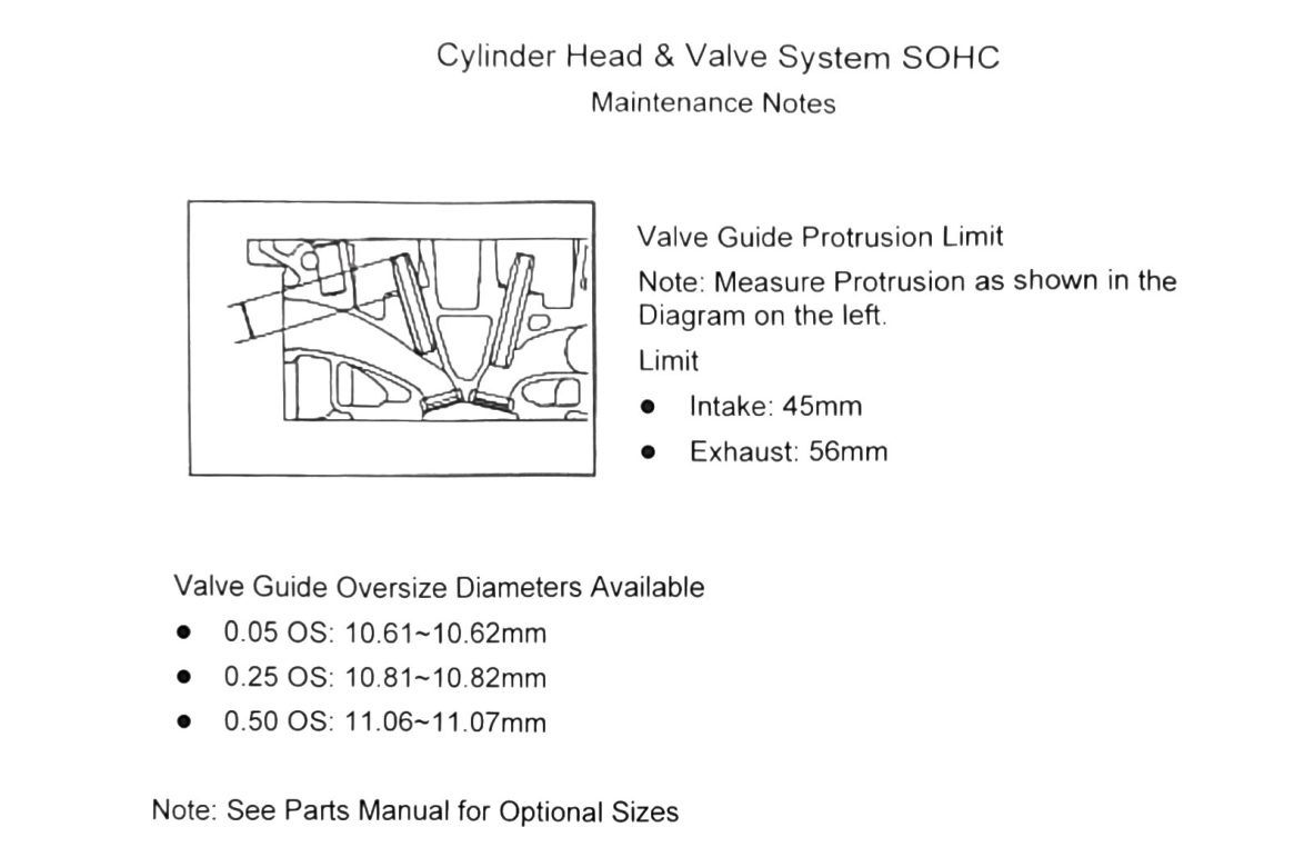
Measure protrusion as shown in the diagram.
| Guide | Protrusion limit |
|---|---|
| Intake | 45mm (1.772in) |
| Exhaust | 56mm (2.205in) |
Valve guide oversize diameters available:
| Oversize | Diameter |
|---|---|
| 0.05 OS | 10.61-10.62mm (0.418in) |
| 0.25 OS | 10.81-10.82mm (0.426in) |
| 0.50 OS | 11.06-11.07mm (0.435–0.436in) |
See Parts Manual for optional sizes.
Valve stem seal installation
Use tool MD999601 to properly install valve stem seals. Coat with engine oil (30W SAE) before installation.