Exhaust Pipe System — SOHC/DOHC
Removal order
Main muffler / rear heat protector:
- Main muffler assembly
- Gasket — discard and replace
- Hanger — inspect and replace if cracked
- Rear heat protector panel
Front exhaust pipe: 5. Front header pipe 6. Gasket — discard and replace 7. Hanger — inspect and replace if defective
Center pipe assembly: 8. Center exhaust pipe 9. Gasket — discard and replace 10. Hanger — inspect and replace if defective 11. Heat protector 12. Exhaust temperature sensor (exhaust overheat panel indicator) 13. Catalytic converter 14. Front heat protector panel
Note: Do not confuse the exhaust temperature sensor with the oxygen sensor. The exhaust temperature sensor only drives a warning-lamp function.
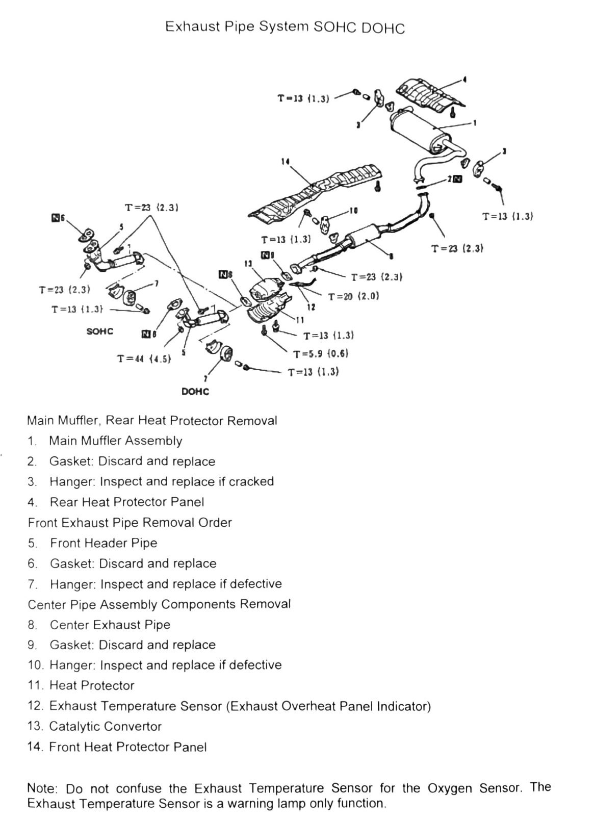
Torque values (as scanned)
Same diagram-mapping problem as the manifold page: numbered torque callouts recovered, but which fastener each applies to (pipe flange nuts, hanger bolts, heat-protector screws, catalytic converter clamps) did not survive OCR. Raw values (kgf·m in parentheses), duplicates as they appeared:
| Value as scanned |
|---|
| T=13 (1.3; 115 in-lb) — appears repeatedly |
| T=23 (2.3; 17 ft-lb) — appears repeatedly |
| T=20 (2.0; 15 ft-lb) |
| T=44 (4.5; 32 ft-lb) |
| T=5.9 (0.6; 52 in-lb) |
A “SOHC” and “DOHC” grouping is present on the page but the callouts are interleaved with unrelated OCR noise (stray numbers “6”, “11”, “26”, “NS”), so a clean per-engine torque table cannot be produced from this scan.
(verify printed p.75) — re-shoot this page to map each torque value to its specific fastener/component and confirm SOHC vs DOHC differences, if any.
Printed p.76 is blank in the scan except for the page number footer — no additional content recovered.