Turbocharger Replacement
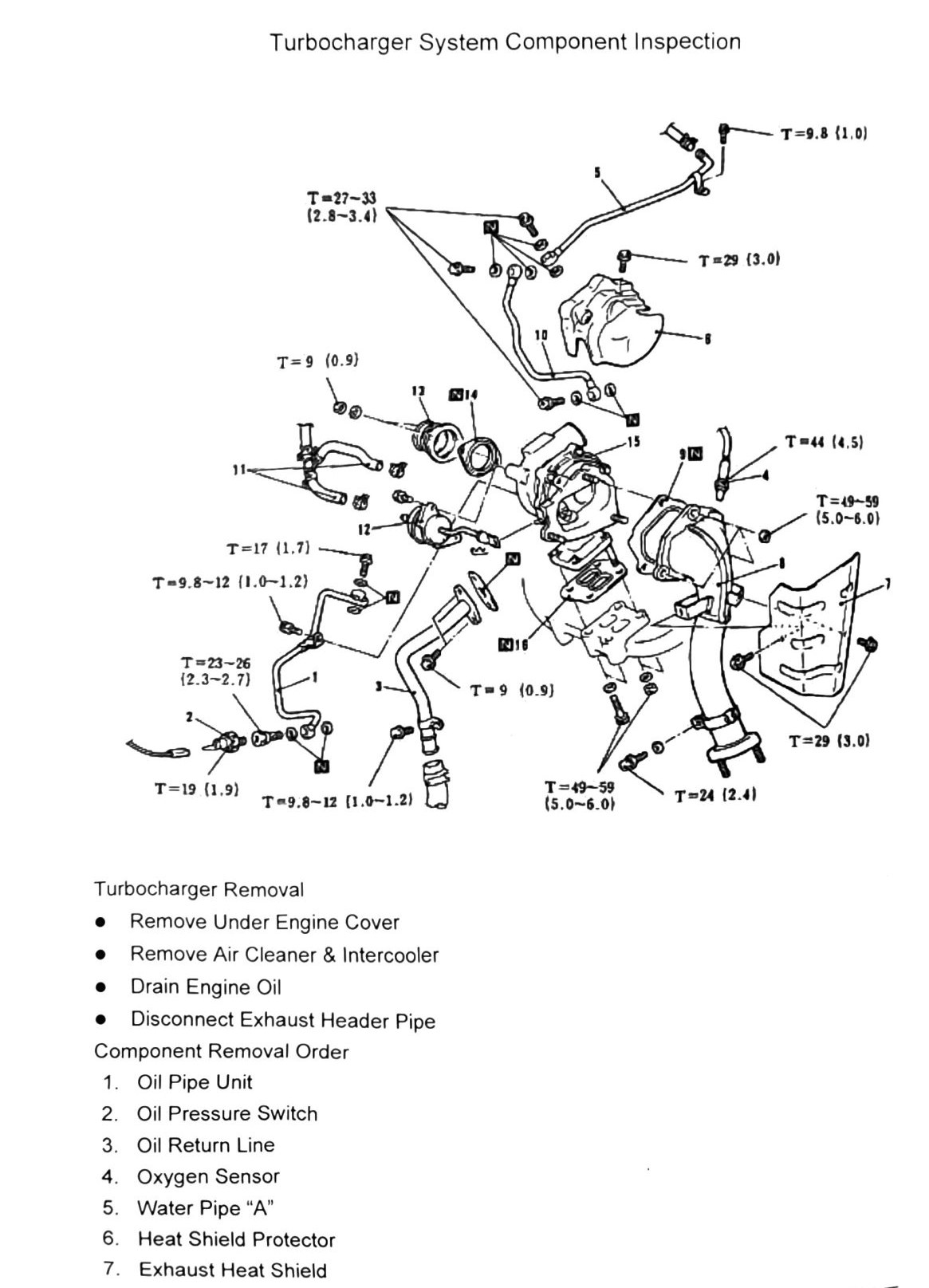
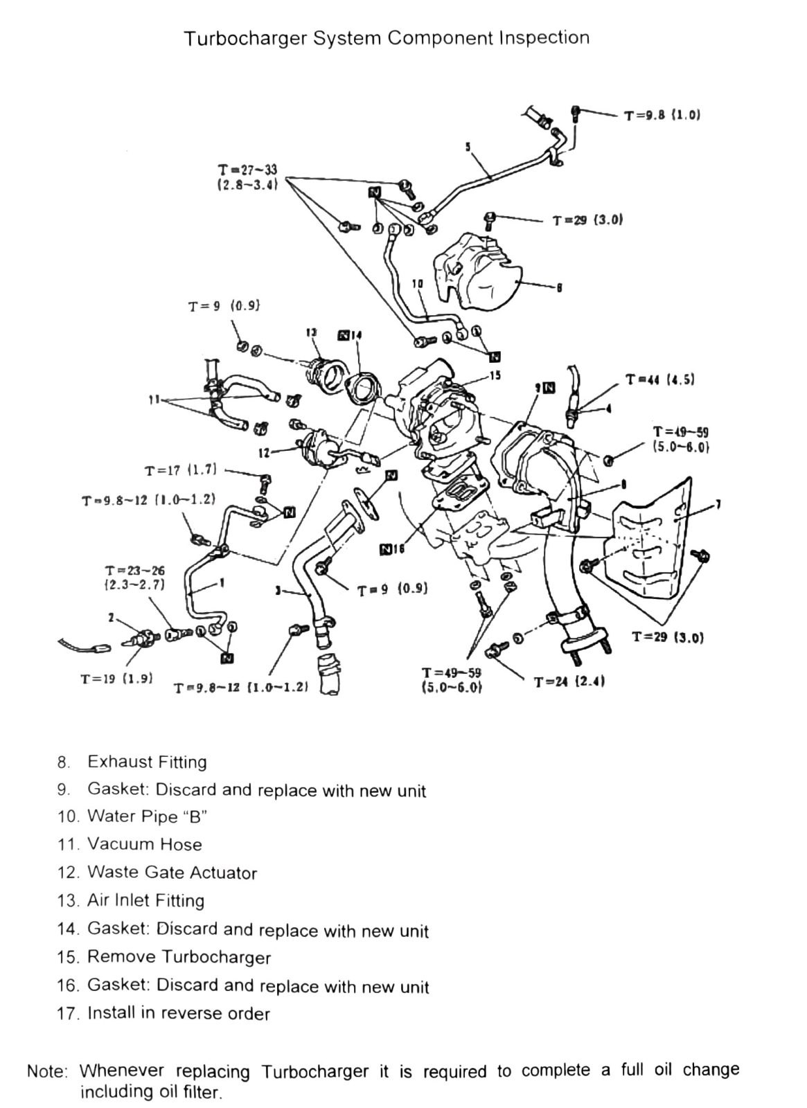
VF25 swap reference note: this is the factory TD04 turbocharger removal/installation procedure. It is the baseline this workspace is using for the oil feed/return and coolant line routing on the VF25 swap. The item numbers below are as legible in the source scan; the torque-to-fastener mapping is not fully recoverable from this OCR pass and every value here needs confirmation against a clean copy of the diagram before being used to torque anything.
Pre-removal
- Remove under engine cover.
Oil system components (items 1-3)
| Item | Description |
|---|---|
| 1 | Oil Pipe Unit |
| 2 | Oil Pressure Switch |
| 3 | Oil Return Line |
(verify printed p.70) — these three items are the turbo oil feed pipe, the oil pressure switch, and the oil return (drain) line. This is exactly the routing detail called out as high-priority for the VF25 swap, and the source scan does not clearly tie a specific torque value to the oil pipe banjo bolt(s) vs. the oil return line fitting. Do not assume a torque value from the table below applies to the oil pipe or oil return line without checking the figure.
Turbocharger removal — component removal order
Preparation:
- Remove Air Cleaner & Intercooler
- Drain Engine Oil
- Disconnect Exhaust Header Pipe
| Item | Description |
|---|---|
| 4 | Oxygen Sensor |
| 5 | Water Pipe “A” |
| 6 | Heat Shield Protector |
| 7 | Exhaust Heat Shield |
| 8 | Exhaust Fitting |
| 9 | Gasket: Discard and replace with new unit |
| 10 | Water Pipe “B” |
| 11 | Vacuum Hose |
| 12 | Waste Gate Actuator |
| 13 | Air Inlet Fitting |
| 14 | Gasket: Discard and replace with new unit |
| 15 | Remove Turbocharger |
| 16 | Gasket: Discard and replace with new unit |
| 17 | Install in reverse order |
(verify printed p.70-71) — item numbering above (4-17) matched clean numeric labels in the scan and is reasonably solid. Note items 5 and 10, “Water Pipe A” and “Water Pipe B” — these are the two turbo coolant lines; confirm which is feed and which is return against the figure before use, as the OCR gives no directional/flow indication beyond the “A”/“B” labels.
Torque specifications
The same diagram (with the same set of torque callouts) is repeated across both pages of this spread.
| Torque callout | N·m (kgf·m) |
|---|---|
| T=9 | (0.9; 80 in-lb) |
| T=9.8 | (1.0; 87 in-lb) |
| T=9.8-12 | (1.0-1.2; 87–106 in-lb) |
| T=17 | (1.7; 150 in-lb) |
| T=19 | (1.9; 168 in-lb) |
| T=23-26 | (2.3-2.7; 17–19 ft-lb) |
| T=24 | (2.4; 18 ft-lb) |
| T=27-33 | (2.8-3.4; 20–24 ft-lb) |
| T=29 | (3.0; 21 ft-lb) |
| T=44 | (4.5; 32 ft-lb) |
| T=49-59 | (5.0-6.0; 36–44 ft-lb) |
(verify printed p.70-71) — this is the full set of distinct torque values legible on the two-page turbocharger removal diagram. None of them could be reliably tied to a specific fastener (oil pipe banjo bolts, water pipe fittings, turbo-to-manifold mounting nuts, exhaust fitting nuts, etc.) from the OCR text alone — the diagram uses leader lines to a numbered parts key that did not survive the scan as machine-readable text. Given this documents the factory oil/coolant line hardware feeding the reference build for the VF25 swap, treat every value in this table as unconfirmed until checked against the source figure or a clean scan. Two additional fastener-size markings, transcribed as “N16” and “N6”, also appear on the diagram and most likely denote bolt/nut head sizes rather than torque values, but this is unconfirmed.
Two callouts also appeared as bare “T=29 (3.0)” values near the “Component Removal Order” heading and the drain/disconnect bullet list, separate from the main parts-key set above; these are included in the table (not double-counted as separate values) but their exact position on the diagram is likewise unconfirmed.
Notes
- Whenever replacing the turbocharger, a full oil change including the oil filter is required.
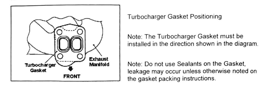
- Turbocharger gasket positioning: the turbocharger gasket must be installed in the direction shown in the diagram — the figure marks the exhaust manifold side as “FRONT”. (verify printed p.72) — the orientation diagram itself did not survive OCR as text; confirm the gasket orientation visually against the figure or a new-old-stock gasket’s own markings before installing.
- Do not use sealants on the turbocharger gasket — leakage may occur unless otherwise noted on the gasket’s own packing instructions.
Torque map — RESOLVED by direct diagram read (2026-08-30)
The p.70–71 figure was rendered at 200 dpi and read visually by the supervisor; leader lines mapped as follows. Items marked ◐ have a leader that is positionally clear but crosses other lines — sanity-check against the printed figure before final torque.
| Fastener | Torque N·m (kgf·m) | Read confidence |
|---|---|---|
| Oxygen sensor (item 4) | 44 (4.5; 32 ft-lb) | ✅ direct leader |
| Oil pressure switch (item 2) | 19 (1.9; 168 in-lb) | ✅ direct leader |
| Oil pipe unit union at pressure-switch tee (item 1) | 23–26 (2.3–2.7; 17–19 ft-lb) | ✅ direct leader |
| Oil pipe unit lower union at block / oil return line lower fitting (items 1, 3) | 9.8–12 (1.0–1.2; 87–106 in-lb) | ✅ two callouts, one each |
| Oil return line upper flange bolt (item 3) | 9 (0.9; 80 in-lb) | ◐ |
| Water pipe “A” end fitting (item 5) | 9.8 (1.0; 87 in-lb) | ✅ direct leader |
| Water/oil pipe banjo-union bolts, upper cluster (items 5, 10 junctions) | 27–33 (2.8–3.4; 20–24 ft-lb) | ◐ multi-leader fan |
| Oil pipe support bracket bolt | 17 (1.7; 150 in-lb) | ◐ |
| Heat shield protector bolt (item 6) | 29 (3.0; 21 ft-lb) | ✅ direct leader |
| Exhaust heat shield / downpipe clamp area bolt (item 7 area) | 29 (3.0; 21 ft-lb) | ◐ second occurrence |
| Turbo ↔ exhaust fitting mounting nuts (items 8, 15) | 49–59 (5.0–6.0; 36–44 ft-lb) | ✅ two callouts, studs both sides |
| Exhaust fitting stud/bolt, lower (item 8 area) | 24 (2.4; 18 ft-lb) | ◐ |
| Small hose-clamp screws near vacuum hose (item 11 area) | 9 (0.9; 80 in-lb) | ◐ |
“N” boxes in the figure = non-reusable parts (Mitsubishi convention), matching key items 9, 14, 16: Gasket — discard and replace with new unit. The OCR fragments earlier transcribed as “N16”/“N6” were these markers, not fastener sizes.
Full parts key (from p.71): 1 Oil Pipe Unit · 2 Oil Pressure Switch · 3 Oil Return Line · 4 Oxygen Sensor · 5 Water Pipe “A” · 6 Heat Shield Protector · 7 Exhaust Heat Shield · 8 Exhaust Fitting · 9 Gasket (NEW) · 10 Water Pipe “B” · 11 Vacuum Hose · 12 Waste Gate Actuator · 13 Air Inlet Fitting · 14 Gasket (NEW) · 15 Turbocharger · 16 Gasket (NEW) · 17 Install in reverse order.
Factory note (p.71, verbatim): “Whenever replacing Turbocharger it is required to complete a full oil change including oil filter.” — applies to the VF25 swap day.