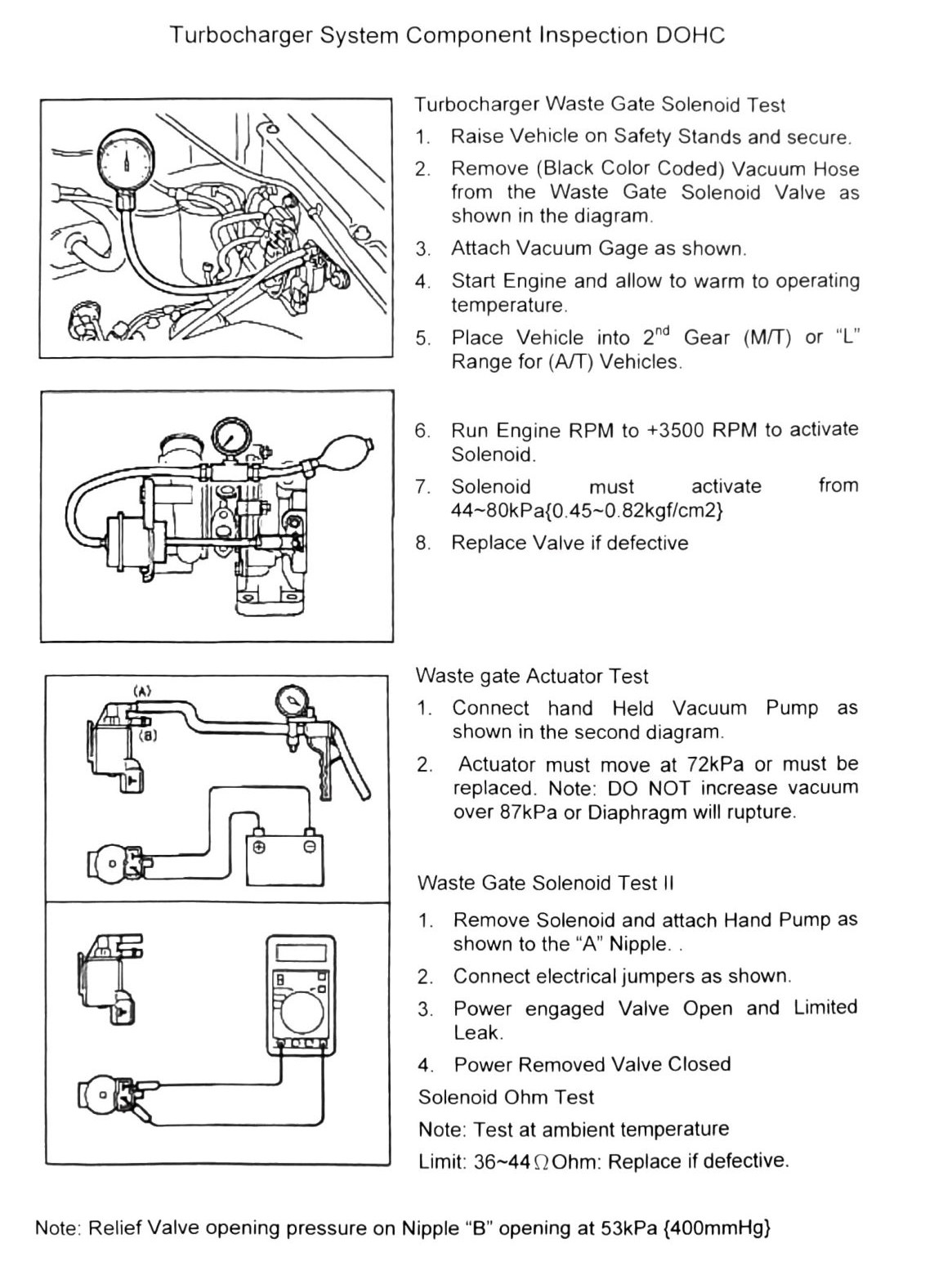
Turbocharger System Component Inspection
DOHC waste gate solenoid, waste gate actuator, and relief valve test procedures. These are the factory TD04-era waste gate control checks — useful as a baseline reference, but the control pressures below are specific to the stock TD04 waste gate hardware and should not be assumed to carry over to a VF25 waste gate actuator without independent verification.
Waste gate solenoid test
- Raise vehicle on safety stands and secure.
- Remove the (black color-coded) vacuum hose from the waste gate solenoid valve as shown in the diagram.
- Attach vacuum gage as shown.
- Start engine and allow to warm to operating temperature.
- Place vehicle into 2nd gear (M/T) or “L” range for A/T vehicles.
- Run engine RPM to +3500 RPM to activate solenoid.
- Solenoid must activate at 44–80 kPa (6.4–12 psi) {0.45–0.82 kgf/cm²}.
- Replace valve if defective.
Waste gate actuator test
- Connect hand-held vacuum pump as shown in the diagram.
- Actuator must move at 72 kPa (10 psi) or must be replaced.
Note: Do NOT increase vacuum over 87 kPa (13 psi) or the diaphragm will rupture.
Waste gate solenoid test II
- Remove solenoid and attach hand pump as shown to the “A” nipple.
- Connect electrical jumpers as shown.
- Power engaged: valve open and limited leak.
- Power removed: valve closed.
Solenoid resistance (ohm) test
Test at ambient temperature.
- Limit: 36–44 Ω (verify printed p.69) — the OCR rendered this as “36-442” with no unit; 36-44 ohms is the most plausible reading given the “Ohm” label on the following line, but the exact figure and unit should be confirmed against a clean copy before use.
- Replace if out of limit.
Relief valve
- Relief valve opening pressure on nipple “B”: opening at 53 kPa (7.7 psi) {400 mmHg}.