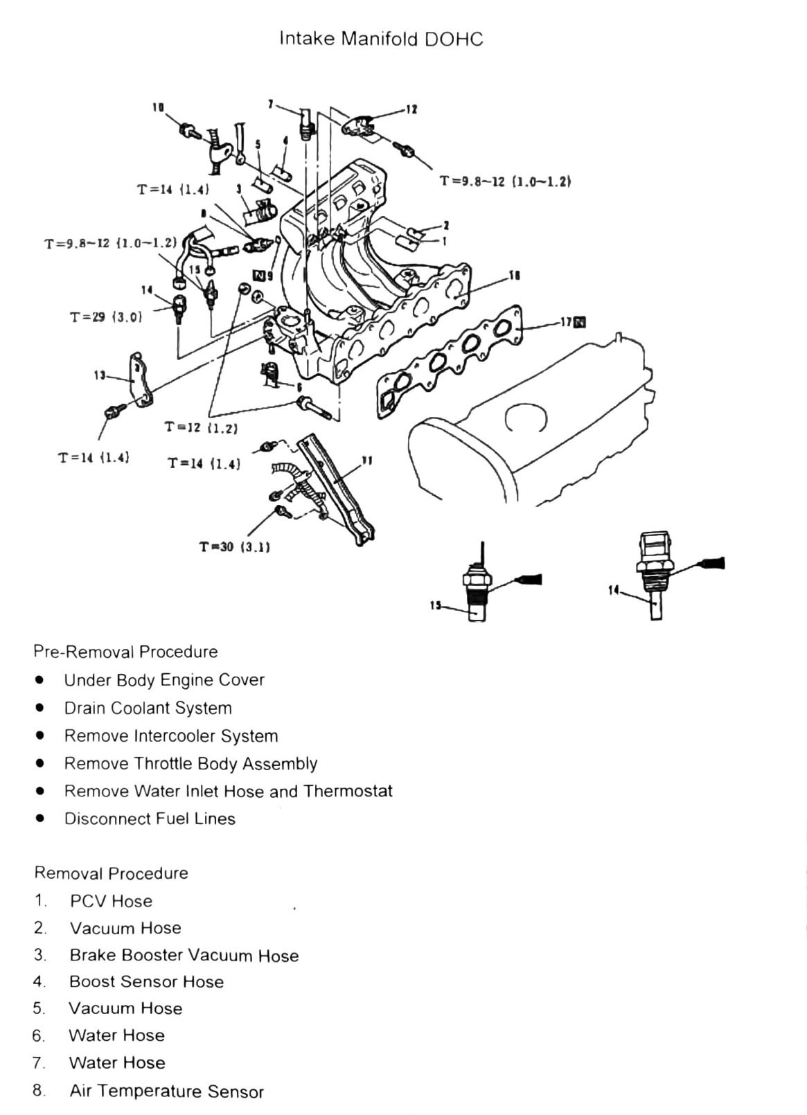
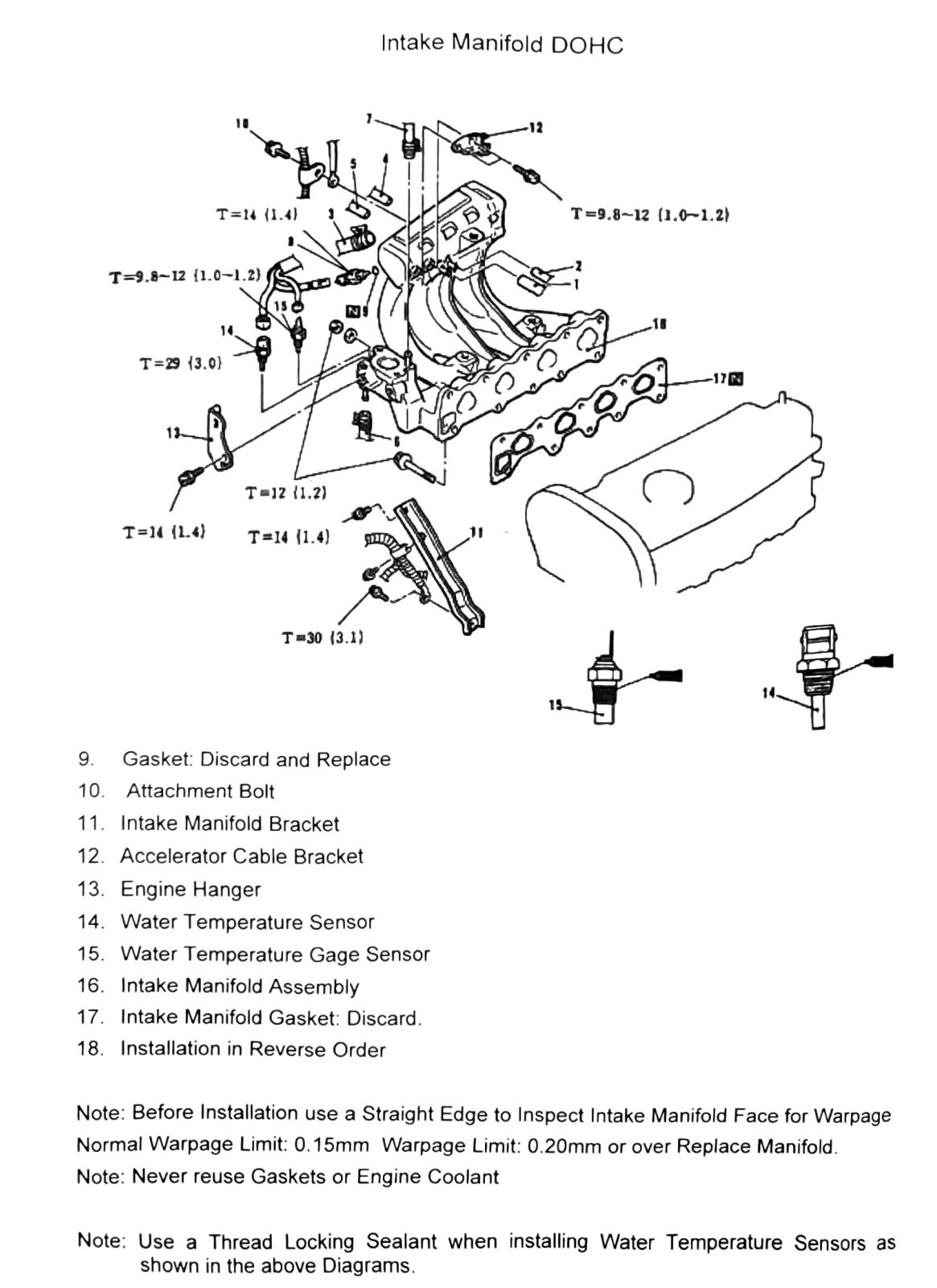
Intake Manifold DOHC
Pre-removal procedure
- Under Body Engine Cover
- Drain Coolant System
- Remove Throttle Body Assembly
- Remove Intercooler System
- Remove Water Inlet Hose and Thermostat
- Disconnect Fuel Lines
Removal procedure, steps 1-8
| Item | Description |
|---|---|
| 1 | PCV Hose |
| 2 | Vacuum Hose |
| 3 | Brake Booster Vacuum Hose |
| 4 | Boost Sensor Hose |
| 5 | Vacuum Hose |
| 6 | Water Hose |
| 7 | Water Hose |
| 8 | Air Temperature Sensor |
(verify printed p.67) — item numbers 4 through 8 were reconstructed by matching bare number markers to the nearest description in the scanned column layout (the OCR separated numbers from their text). Numbers 1-3 are directly attached to their descriptions in the source and are solid.
Removal procedure, steps 9-18 (continued)
| Item | Description |
|---|---|
| 9 | Gasket: Discard and Replace |
| 10 | Attachment Bolt |
| 11 | Intake Manifold Bracket |
| 12 | Accelerator Cable Bracket |
| 13 | Engine Hanger |
| 14 | Water Temperature Sensor |
| 15 | Water Temperature Gage Sensor |
| 16 | Intake Manifold Assembly |
| 17 | Intake Manifold Gasket: Discard |
| 18 | Installation in Reverse Order |
(verify printed p.68) — this page’s numbered callouts were badly scrambled by the OCR column split; items 9 and 10 in particular (“Gasket: Discard and Replace” and “Attachment Bolt”) could not be confirmed against a specific number in the source and may be swapped or misordered. Items 11 through 18 carried clear numeric labels in the scan and are more reliable, but the whole sequence should be checked against a clean copy before use, especially given this documents intake manifold hardware directly adjacent to the turbo oil/coolant lines.
Torque specifications
Same diagram (same callouts) repeated across both pages of this spread.
| Torque callout | N·m (kgf·m) | Count on diagram |
|---|---|---|
| T=9.8-12 (1.0-1.2; 87–106 in-lb) | — | ×2 |
| T=12 (1.2; 106 in-lb) | — | ×1 |
| T=14 (1.4; 124 in-lb) | — | ×3 |
| T=29 (3.0; 21 ft-lb) | — | ×1 |
| T=30 (3.1; 22 ft-lb) | — | ×1 |
(verify printed p.67-68) — as with the SOHC manifold, the exact fastener each torque value applies to is not recoverable from the OCR; confirm against the source figure.
Notes
- Before installation, use a straightedge to inspect the intake manifold face for warpage. Source text: “Normal Warpage Limit: 0.15mm Warpage Limit: 0.20mm or over Replace Manifold.” (verify printed p.68) — the source phrasing gives two numbers without clearly labeling which is the service/replace limit; confirm whether 0.15mm is the normal (as-new) reading and 0.20mm is the replace threshold, or whether these numbers are OCR-duplicated from one limit, before using this as a machining spec.
- Never reuse gaskets or engine coolant.
- Use a thread-locking sealant when installing water temperature sensors, as shown in the diagrams.