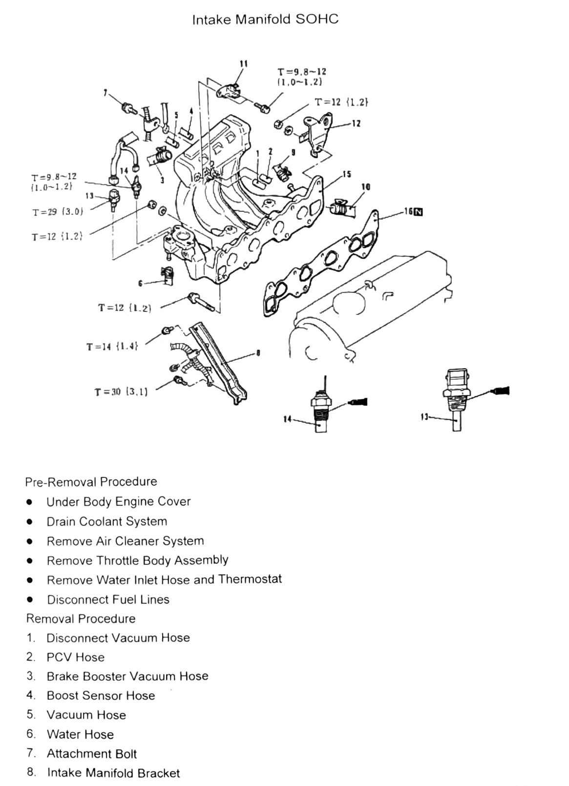
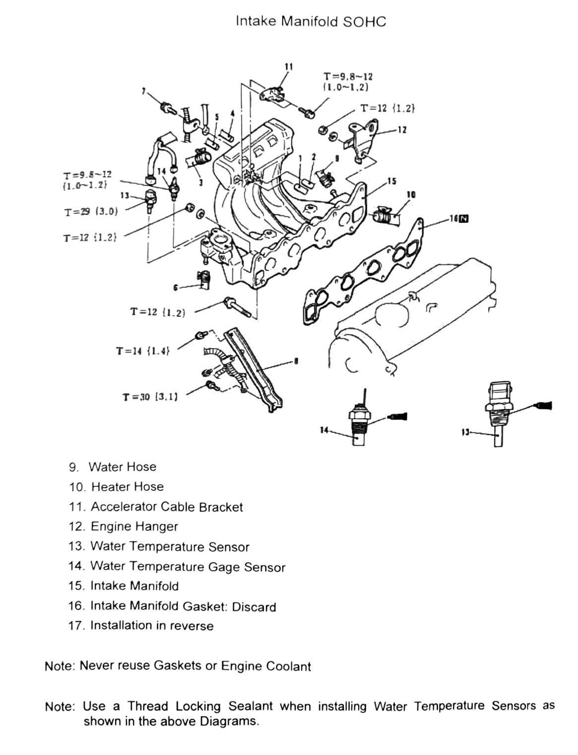
Intake Manifold SOHC
Pre-removal procedure
- Under Body Engine Cover
- Drain Coolant System
- Remove Air Cleaner System
- Remove Throttle Body Assembly
- Remove Water Inlet Hose and Thermostat
- Disconnect Fuel Lines
Removal procedure
| Item | Description |
|---|---|
| 1 | Disconnect Vacuum Hose |
| 2 | PCV Hose |
| 3 | Brake Booster Vacuum Hose |
| 4 | Boost Sensor Hose |
| 5 | Vacuum Hose |
| 6 | Water Hose |
| 7 | Attachment Bolt |
| 8 | Intake Manifold Bracket |
| 9 | Water Hose |
| 10 | Heater Hose |
| 11 | Accelerator Cable Bracket |
| 12 | Engine Hanger |
| 13 | Water Temperature Sensor |
| 14 | Water Temperature Gage Sensor |
| 15 | Intake Manifold |
| 16 | Intake Manifold Gasket: Discard |
| 17 | Installation in reverse |
Torque specifications
The same diagram (with the same torque callouts) is repeated across both source pages of this spread.
| Torque callout | N·m (kgf·m) | Count on diagram |
|---|---|---|
| T=9.8-12 (1.0-1.2; 87–106 in-lb) | — | ×2 |
| T=12 (1.2; 106 in-lb) | — | ×3 |
| T=14 (1.4; 124 in-lb) | — | ×1 |
| T=29 (3.0; 21 ft-lb) | — | ×1 |
| T=30 (3.1; 22 ft-lb) | — | ×1 |
(verify printed p.65-66) — torque values are shown as free-floating callouts around the manifold diagram; the exact fastener each one belongs to (bracket bolts vs. manifold nuts vs. sensor boss) did not survive OCR and must be confirmed against the figure. A bolt/nut size marking transcribed as “16N” also appears near the manifold nuts on both pages — this reads as a fastener size callout, not a torque value, but should be confirmed.
Notes
- Never reuse gaskets or engine coolant.
- Use a thread-locking sealant when installing water temperature sensors, as shown in the diagrams.