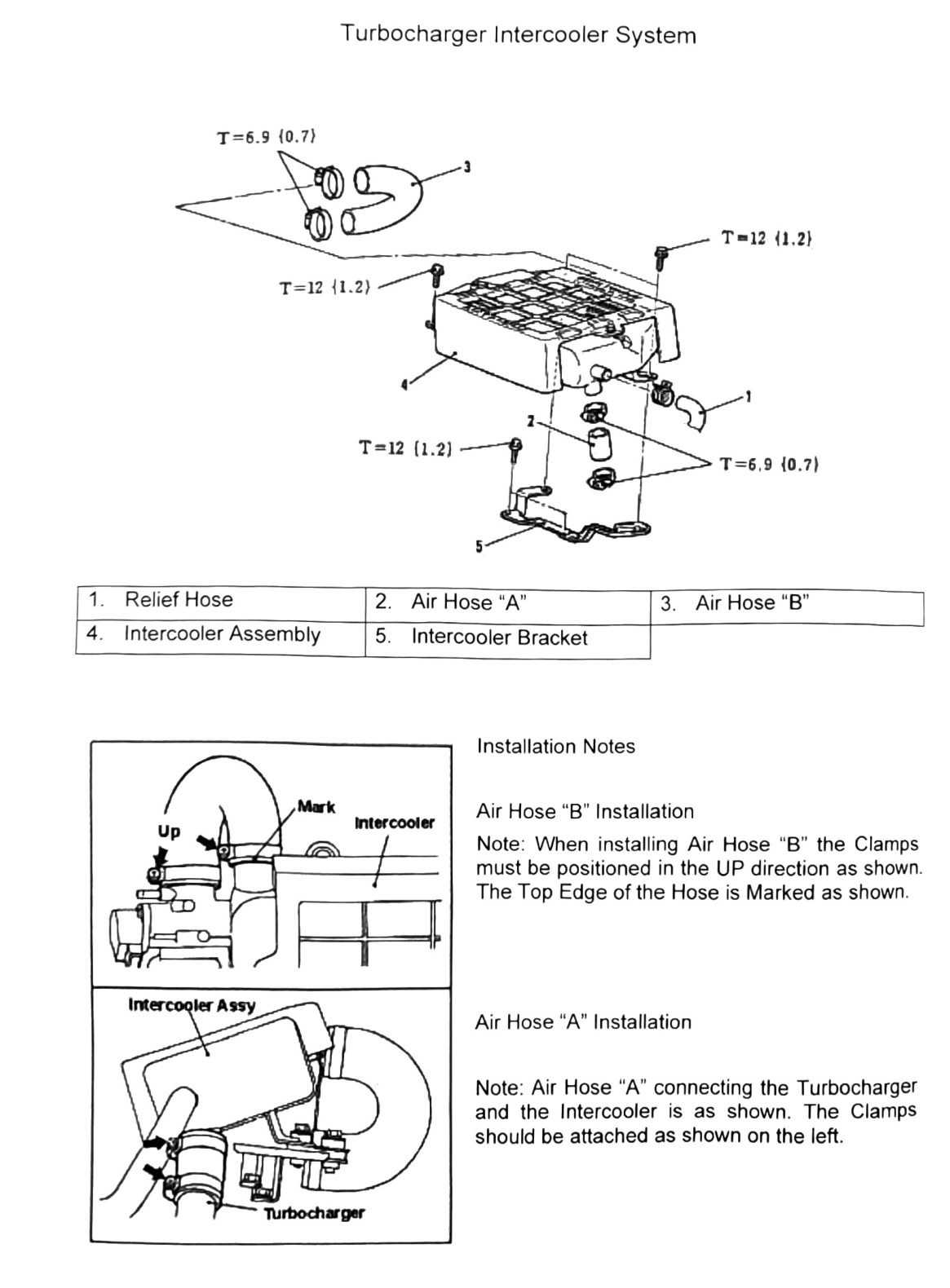
Turbocharger Intercooler System
Covers the intercooler assembly, its mounting bracket, and the two charge-air hoses connecting the turbocharger to the intercooler.
Component list
| Item | Component |
|---|---|
| 1 | Relief Hose |
| 2 | Air Hose “A” |
| 3 | Air Hose “B” |
| 4 | Intercooler Assembly |
| 5 | Intercooler Bracket |
Torque specifications
| Torque callout | N·m (kgf·m) | Count on diagram |
|---|---|---|
| Clamp/fastener | T=6.9 (0.7; 61 in-lb) | ×2 |
| Clamp/fastener | T=12 (1.2; 106 in-lb) | ×3 |
(verify printed p.64) — five torque callouts are shown against five listed components/hoses, but the OCR did not preserve which callout lines up with which item. Confirm against the source figure before torquing any clamp or bracket bolt.
Installation notes
- Air Hose “B” installation: Clamps must be positioned in the UP direction as shown in the diagram. The top edge of the hose is marked as shown.
- Air Hose “A” installation: Air Hose “A” connects the turbocharger and the intercooler as shown; clamps should be attached as shown in the diagram.
- The Intercooler Assembly has an “Up” mark that must be observed on installation.