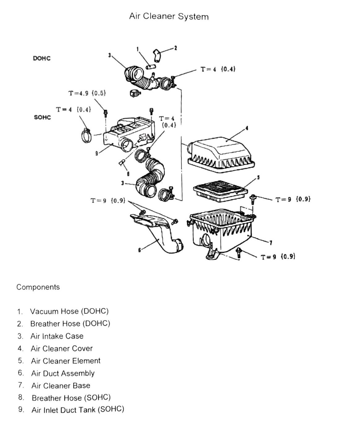
Air Cleaner System Components
The air cleaner assembly differs between the naturally aspirated SOHC engine and the turbocharged DOHC engine, primarily in the breather/vacuum hose routing and the inlet duct arrangement.
Component list
| Item | Component | Applies to |
|---|---|---|
| 1 | Vacuum Hose | DOHC |
| 2 | Breather Hose | DOHC |
| 3 | Air Intake Case | Both |
| 4 | Air Cleaner Cover | Both |
| 5 | Air Cleaner Element | Both |
| 6 | Air Duct Assembly | Both |
| 7 | Air Cleaner Base | Both |
| 8 | Breather Hose | SOHC |
| 9 | Air Inlet Duct Tank | SOHC |
Torque specifications
The source diagram shows torque callouts scattered around the DOHC and SOHC clamp/fastener locations without a clean line-by-line mapping to the component list above.
| Torque callout | N·m (kgf·m) |
|---|---|
| DOHC | T=4 (0.4; 35 in-lb) |
| DOHC | T=4.9 (0.5; 43 in-lb) |
| DOHC | T=4 (0.4; 35 in-lb) |
| SOHC | T=4 (0.4; 35 in-lb) |
| SOHC | T=9 (0.9; 80 in-lb) |
| SOHC | T=9 (0.9; 80 in-lb) |
| (unlabeled, near “Components” callout) | T=9 (0.9; 80 in-lb) |
(verify printed p.63) — which specific hose clamp or fastener each torque value applies to could not be confirmed from the OCR; the figure ties values to positions on the diagram that did not survive the scan. Do not apply these values to a fastener without checking the source figure.