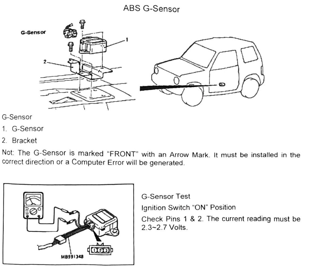
ABS G-Sensor
Components
| Item | Description |
|---|---|
| 1 | G-Sensor |
| 2 | Bracket |
Note: the G-sensor is marked “FRONT” with an arrow mark. It must be installed in the correct direction or a computer error will be generated.
G-sensor test
With the ignition switch in the “ON” position, check pins 1 and 2. The current reading must be 2.3-2.7 Volts.
Special tool referenced in the diagram: MB991348.