ABS Speed Sensor
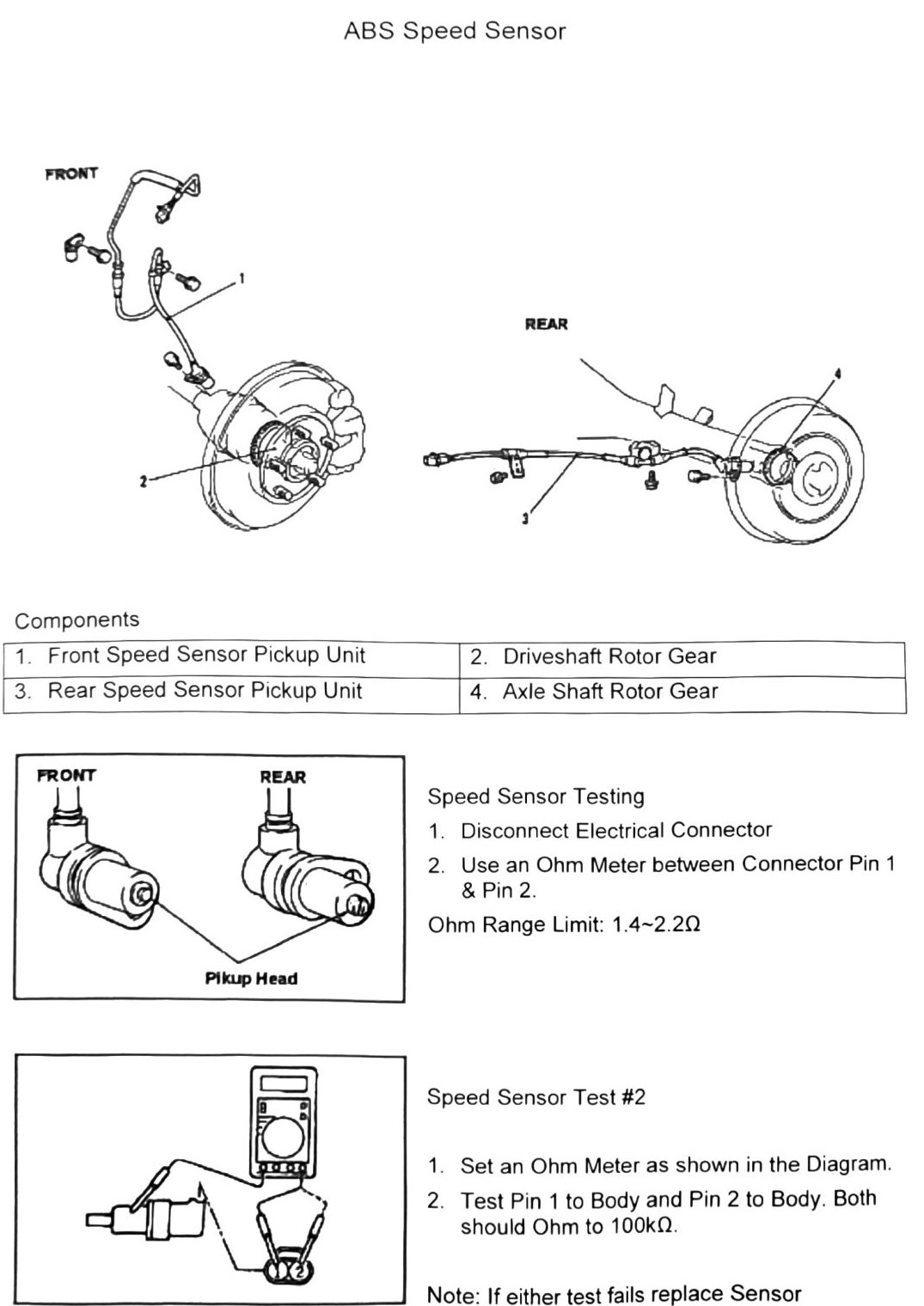
Components
| Item | Description |
|---|---|
| 1 | Front Speed Sensor Pickup Unit |
| 2 | Driveshaft Rotor Gear |
| 3 | Rear Speed Sensor Pickup Unit |
| 4 | Axle Shaft Rotor Gear |
Speed sensor testing
- Disconnect electrical connector.
- Use an ohm meter between connector pin 1 and pin 2.
- Ohm range limit: 1.4-2.2Ω
(verify printed p.282) — the resistance range was transcribed by OCR as “1.4-2.20”; this is almost certainly “1.4-2.2Ω” with the ohm symbol misread as a zero, but confirm against the source figure before treating the trailing digit as part of the number.
Speed sensor test #2
- Set an ohm meter as shown in the diagram.
- Test pin 1 to body and pin 2 to body. Both should read 100kΩ.
Note: if either test fails, replace sensor.