Master Cylinder Overhaul: Standard
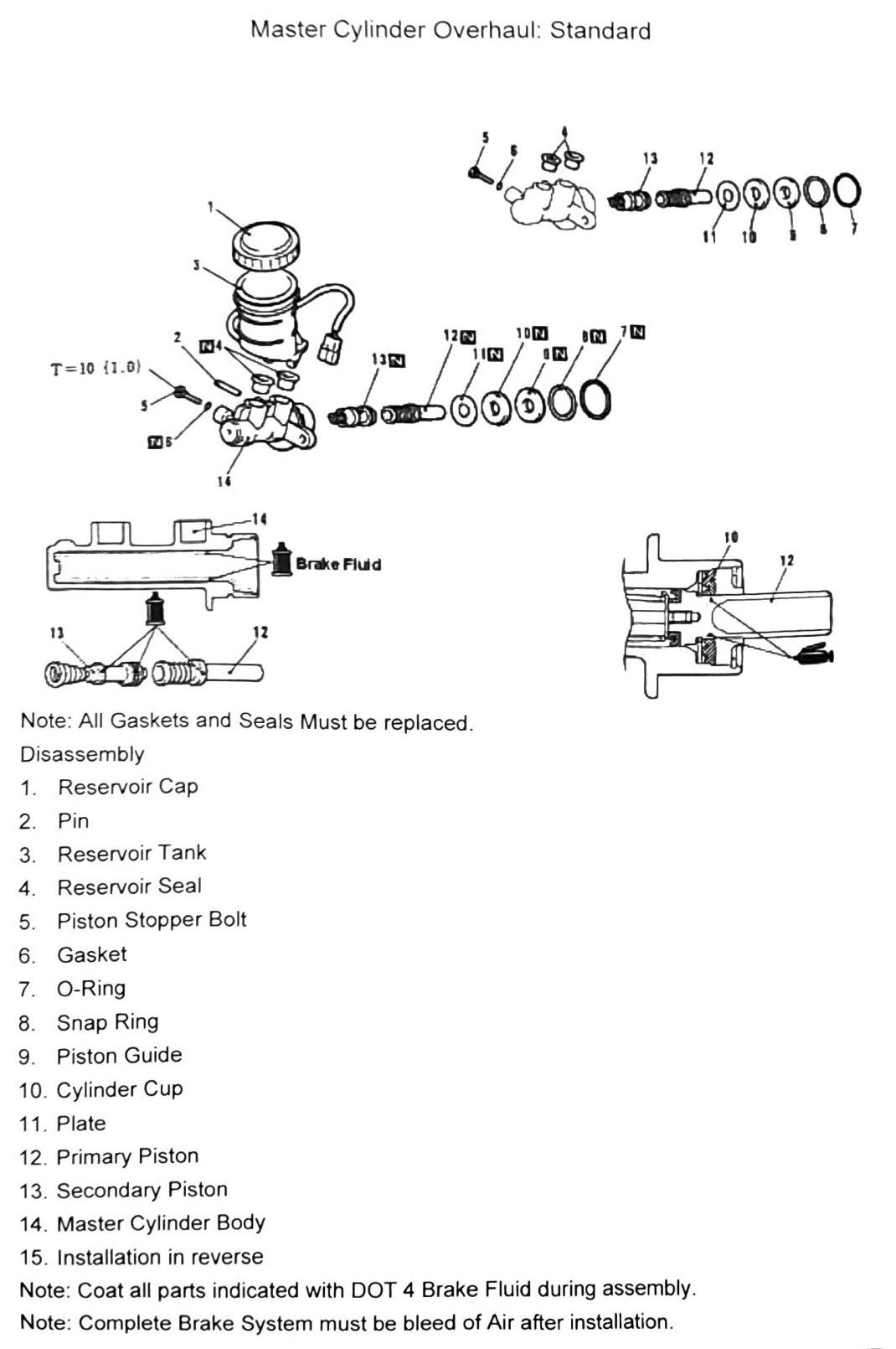
Note: all gaskets and seals must be replaced. Coat all parts indicated with DOT 4 brake fluid during assembly. The complete brake system must be bled of air after installation.
Disassembly (exploded view)
| Item | Description |
|---|---|
| 1 | Reservoir Cap |
| 2 | Pin |
| 3 | Reservoir Tank |
| 4 | Reservoir Seal |
| 5 | Piston Stopper Bolt |
| 6 | Gasket |
| 7 | O-Ring |
| 8 | Snap Ring |
| 9 | Piston Guide |
| 10 | Cylinder Cup |
| 11 | Plate |
| 12 | Primary Piston |
| 13 | Secondary Piston |
| 14 | Master Cylinder Body |
| 15 | Installation in reverse |
Torque specification
| Torque callout | N·m (kgf·m) | in-lb |
|---|---|---|
| T=10 | (1.0) | 89 |
(verify printed p.272) — the single torque callout on this diagram could not be confidently matched to a specific item number (most likely the piston stopper bolt, item 5, but this is not confirmed).
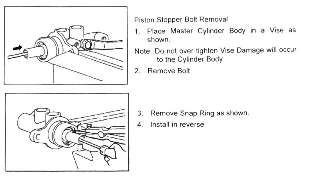
Piston stopper bolt removal
- Place master cylinder body in a vise as shown.
Note: do not over-tighten the vise — damage will occur to the cylinder body.
- Remove bolt.
- Remove snap ring as shown.
- Install in reverse.